this almost certainly fits into the hum loop that is described by D.JoffeOK, we've made some progress in taming the hum, but not completely. We rotated the transformers which helped some. Then we changed the input wires to shielded twisted pairs (drain wire connected to chassis ground), which didn't seem to change anything.
There is no hum when the input cables are not connected.
There is no hum when the inputs are shorted.
There is no hum when the input cables are connected to the F5, but not to a source (this is a change from earlier attempts; rotating the transformers seems to have quieted the hum that was there with just the cables connected).
There IS a hum when the input cables are connected to a source (i.e., tube preamp), even if the source is not powered up or if the IEC connector is completely disconnected from the source.
We picked up a used oscilloscope, but don't know yet how to derive meaningful data from the squiggly lines. Once we've figured that out, I'll post what we find. In the meantime, does any of the above info suggest a possible cause/solution?
Thanks...
Adopt his Fig5 solution.
Thanks Andrew. So, assuming you're correct, is it safe to say that the source of the hum is in the preamp, as described by Joffe at the end of his article, since the hum is only present when the F5 is connected to the preamp? Joffe appears to say that his remedy, applied to just the power amp, will address this also. Am I correct?
So if I'm reading the schematic correctly, it appears like we need to connect a 10R between input ground and output ground, at the jacks. We tried that, and it did not reduce the hum. Please let me know if I've got the location of the resistor wrong.
Currently, the only ground connections are the safety earth, and the PSU ground buss connected to the chassis via the CL60. (Of course, the amp PCB grounds are connected to the PSU grounds).
The hum actually is very faint, and the amp is very listenable as-is. But since we know it's capable of dead silent operation, we'd like to achieve that... We're 99% there, and as usual the last 1% is proving to be the most difficult to overcome.
Changed the parallel resistors to 4k7, this leads to max 550mV with zero offset. Amp sounds soft and clear with no distortion. Should I change the resistors to 5k6?
Yes, increase resistor until you can bias a little more than .6V
But to get to 550mV one poti is totally open, the other just one third. Will this lead to any problems? I'm new to fets, sorry for this noob question...
No problems - it's actually quite normal.
The only thing that maters now is bias and offset stability with the lid on. If you can get .6V bias, zero offset, and has minimum drift once powered on for 30min, it's good!!
No.Thanks Andrew. So, assuming you're correct, is it safe to say that the source of the hum is in the preamp, as described by Joffe at the end of his article, since the hum is only present when the F5 is connected to the preamp? Joffe appears to say that his remedy, applied to just the power amp, will address this also. Am I correct?
The hum is created by the interference current flowing around the LOOP. That LOOP is in the Power Amplifier and the interconnect cable and the Source equipment. It is the topology of the system that is allowing the interference current to flow around the LOOP. You cannot point the "blame" at one component. If you used a Monoblock Power Amplifier the LOOP does not exist. The interference current cannot flow around the broken LOOP. and that results in no hum for the system.
This is why I have been recommending for quite a few years that a multi-channel Power Amplifier should have a resistor/diode connection between the Signal Return/ground and the Power Ground on each PCB whereas in a MONOBLOCK PCB one can have a direct connection between Signal Return/ground and Power Ground.
No. It's the HBRR and HBRL resistors that need to be added to attenuate the interference current flowing around the LOOP.So if I'm reading the schematic correctly, it appears like we need to connect a 10R between input ground and output ground, at the jacks. We tried that, and it did not reduce the hum. Please let me know if I've got the location of the resistor wrong.
Measure the Hum+Noise at the output.Currently, the only ground connections are the safety earth, and the PSU ground buss connected to the chassis via the CL60. (Of course, the amp PCB grounds are connected to the PSU grounds).
The hum actually is very faint, and the amp is very listenable as-is. But since we know it's capable of dead silent operation, we'd like to achieve that... We're 99% there, and as usual the last 1% is proving to be the most difficult to overcome.
That is the ONLY sensible way to make comparisons between different solutions.
Last edited:
This is why I have been recommending for quite a few years that a multi-channel Power Amplifier should have a resistor/diode connection between the Signal Return/ground and the Power Ground on each PCB
This sounds like a good solution! Would you please illustrate exactly what you mean?
MTM DESIGN WITH PRO DRIVERS
Hı. Is it a good idea to make a MTM design with 97 dB B&C 20 cm Woofers and DE500 or (maybe De250 ) horn driver ? I do not want to make a speaker more than 25cm width (because of WAF) I will use a good quality 12 inch diy subwoofer with B&W spare sub driver (furniture looking)below 100hz with class d 500w Iraudamp7. It will be a 2.1 system
Does these drivers give good sound at @ 1w and 5w
Or do they give distortion at low power levels ?I read that Gedlee speakers are good at more than 100w power
Should i buy AER MK2 or LOWTHER ?
It is because I can find pro drivers at good prices in my country
I can use 6 monoblock F5 amps without preamp maybe.I want to use only B1 buffer in front .And an active crossover with Hq opamps and Hq mkp1837 caps.So no additional gain may make sound better
Thanks
Last edited:
I have been recommending for quite a few years that a multi-channel Power Amplifier should have a resistor/diode connection between the Signal Return/ground and the Power Ground on each PCB, whereas in a MONOBLOCK PCB one can have a direct connection between Signal Return/ground and Power Ground.
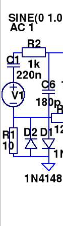
download D.Joffe's paper.This sounds like a good solution! Would you please illustrate exactly what you mean?
He describes via diagram the problem (interference currents flowing around LOOPs) and then shows the solution (attenuating the interference current) by inserting an added resistor.
In fig5 the two added resistors for the two channel amplifier are HBRR & HBRL
If you extract that information and apply it to a PCB layout that could be used in a monoblock amplifier and in a multi-channel amplifier, then you will see that each amplifier has one added resistor.
When building a stereo amplifier each PCB gets the added resistor, typically 10r. Some have used other values I have seen as low as 1r0 and as high as 100r, so there seems to be a lot of leeway in choosing a value.
When building a Monoblock the resistor position is filled with a shorting link (zero ohms jumper).
That resistor is between the Signal Return and the Power Ground. But look carefully at D.Joffe's diagram. Identify the Signal Circuit. The resistor is NOT in the route of the signal around the signal circuit.
The added resistor is in the LINK between the Signal Circuit and the Power Ground.
This link is a voltage reference link that allows the amplifier to reference the input to the output. It only carries interference current. I have never been able to measure any voltage across the added resistor, there is no measurable signal current along that link.
One final message - SAFETY
The Signal Ground links a Source to the Receiver.
If the Source develops a Mains Fault and does not have a PE connection to blow the Mains fuse (all ClassII equipment) then that Fault current can enter the Receiver via the interconnect. The Receiver PE connection will harmlessly divert the Fault current to "Earth" through the "grounding" path inside the Receiver. The added resistor HBRR is in that route. it must be able to pass Fault current in the Source until the Mains fuse ruptures. The added resistor should have inverse parallel diodes across it.
A 1n4002 which has only a 1A rating can pass >30A as a short term transient and can probably pass >100Apk as a one shot "life saver" to blow the mains fuse.
This is another reason for close rating mains fuses.
A close rated fuse ruptures much more quickly than a "normal" fuse when subjected to fault current situation. From the manufacturer's graphs I have estimated that a close rated fuse blows about five to ten times faster than a 3 times larger fuse.
Last edited:
The first result from google
And Bonzai found the paper
http://www.diyaudio.com/forums/analog-line-level/265232-comment-grounding-scheme-11.html#post4170245
But in Bonzai's HiFisonix paper on amplifier wiring, the added resistor is inserted in the wrong location. It is in the signal route, instead of in the LINK from signal route to Power Ground.
D.Joffe's paper on interference in ground loops
http://www.updatemydynaco.com/documents/GroundingProblemsRev1p4.pdf
Salas hotrodded blue DCB1 build - Page 485 - diyAudio
www.diyaudio.com › Forums › Source & Line › Analog Line Level
4 days ago - 10 posts - 5 authors
Wher can I read about The standard D.Joffe explained solution?
F5 power amplifier - Page 1463
6 posts
27 Jan 2015
Salas hotrodded blue DCB1 build - Page 484
10 posts
25 Jan 2015
LM3886 surround amp; problems with 50Hz noise
8 posts
18 Jan 2015
Akitika PR101 Preamp by Dan Joffe
2 posts
1 Oct 2014
More results from www.diyaudio.com
And Bonzai found the paper
http://www.diyaudio.com/forums/analog-line-level/265232-comment-grounding-scheme-11.html#post4170245
But in Bonzai's HiFisonix paper on amplifier wiring, the added resistor is inserted in the wrong location. It is in the signal route, instead of in the LINK from signal route to Power Ground.
D.Joffe's paper on interference in ground loops
http://www.updatemydynaco.com/documents/GroundingProblemsRev1p4.pdf
Last edited:
which one?
By now, hopefully, both of you realise how nondescript "D.Joffe paper ... interference currents..." is for someone that hears about it for the first time.
So instead of wasting time with "F" grade attempts at sarcastic humour, just pasting a URL would be much more efficient (and equally humourless) AND appreciated.
Thanks for the link Andrew!
So instead of wasting time with "F" grade attempts at sarcastic humour, just pasting a URL would be much more efficient (and equally humourless) AND appreciated.
Thanks for the link Andrew!
For the record, I was able to quickly find the Joffe paper, no problem. Trying to interpret it is the real challenge. I'm new to this, coming up on 50 years old, so my ability to learn new stuff isn't what it used to be. Most of my brain cells are either dried and shriveled up, or caught up in trying to figure out ways to keep the kids off my lawn .
Thank you Andrew for taking up so much of your time trying to enlighten us.
I've searched a bunch of other posts addressing hum/noise, and the Joffe solution in particular. I THINK I've gleaned the solution from one of your posts in another thread; again please correct me if I'm wrong.
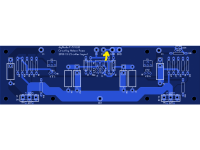
See my attached picture of the F5 V.3 PCB. If I understand you correctly, I am to cut the trace between the input ground and the power ground, indicated by the crudely-drawn arrow, and then connect the now separated ground points with one resistor (say 10R) and two power diodes. All three components should be parallel, and the diodes should be inverse to one another.
Am I headed in the right direction?
.Thank you Andrew for taking up so much of your time trying to enlighten us.
I've searched a bunch of other posts addressing hum/noise, and the Joffe solution in particular. I THINK I've gleaned the solution from one of your posts in another thread; again please correct me if I'm wrong.
See my attached picture of the F5 V.3 PCB. If I understand you correctly, I am to cut the trace between the input ground and the power ground, indicated by the crudely-drawn arrow, and then connect the now separated ground points with one resistor (say 10R) and two power diodes. All three components should be parallel, and the diodes should be inverse to one another.
Am I headed in the right direction?
Attachments
I could draw it, but that won't help you, since I can't show you any of my drawings.
This one? Robbed from http://www.diyaudio.com/forums/solid-state/100736-mullard-ss-power-amplifier-6.html#post1526992, also a nice sounding design.
Attachments
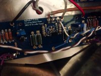
See the attached pic. The input + and gnd are connected to the ground points labeled as such on the board. The next white wire is the output gnd, and the white wire after that is gnd from the PSU.
This is the diyAudio store's current version of the F5 board, and I'm guessing most less-skilled F5 builders such as myself would use this board, so being able to see where precisely on the board to put the hum-breaking resistor (and the diodes) would be helpful to many people.
Is it safe to presume that this is the correct location (on this board) for the HBR, regardless of where in the signal path the ground inductor(s) occur? Should provisions for HBRs be included in the next version of the F5 boards?
Finally, elsewhere you've stated that other values for the HBRs could be used, and that 1N4002 diodes would be suitable. I've got 7.5R resistors and KR4002 diodes on hand. Am I good to go? I.E., is it safe to presume that *4002 are roughly comparable to 1N4002? If not, I can probably get them at the RShack around the corner...
Attachments
- Home
- Amplifiers
- Pass Labs
- F5 power amplifier