'shaving' mica seems kind of difficult while keeping a flat surface. Stuff looks like if flakes off in patchy ways sometimes...
What's the thinnest one can go?
What's the thinnest one can go?
Alternative is to look for the best mica and shave it as thin as you can.
Mica quality varies, depending on the origin location.
Does require patience and a steady hand.
(by coincidence, I eyeballed a lot of mica at the geology faculty of the Amsterdam university, studied physical geography there)
http://www.conrad.de/ce/de/product/...6451F7C770826542F03E756503.ASTPCEN14?ref=list
Plenty of other dealers.
Ask those who build the F5X.
Patrick
Plenty of other dealers.
Ask those who build the F5X.
Patrick
It is pretty easy to get to 1 milli-inch (or thinner) with good mica. I use an exacto-knife, a good light source, and a steady hand. After a little practice it is pretty easy to do. Often I can get two or three usable insulators starting from a single thicker piece.
'shaving' mica seems kind of difficult while keeping a flat surface. Stuff looks like if flakes off in patchy ways sometimes...
What's the thinnest one can go?
Thanks for the link.
But Out of Stock - no news since Sept 2013
The diyAudio warehouse is changing physical location. While everything is in transit from the original location to the new, it will show as out of stock.
Things are planned to be back on-line by May 1.
Newbie Question - Adding Output Devices to R1 - heat vs distortion
Hello,
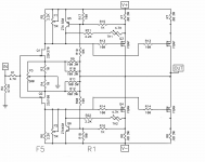
Looking at the Turbo and since my PCB's have room for extra output devices (CVILLER), I was thinking of adding one extra set of output devices per channel without increasing the power supply voltage.
I was hoping that:
1. Lower heatsink (better spread of dissipation between 4 devices)
2. Lower distortion (???)
Am I right?
If so, then is the schematic attached ok? (R1 version)
Hello,
Looking at the Turbo and since my PCB's have room for extra output devices (CVILLER), I was thinking of adding one extra set of output devices per channel without increasing the power supply voltage.
I was hoping that:
1. Lower heatsink (better spread of dissipation between 4 devices)
2. Lower distortion (???)
Am I right?
If so, then is the schematic attached ok? (R1 version)
Attachments
just go for it
prior to powering up , back up with trimpots to zero bias (confirm min. pot value with ohmmeter across R5,R6 !!) , then proceed with biasing/offset procedure as you already did with original
stop at whatever you reach first - max temp on heatsinks ( 55C in summer room temp) or , say, 35W dissipation per mosfet
I hope you calculate that PSU is capable of feeding more current to OS
Thanks,
I was thinking to stay at 25W total, so no extra current, but only benefit from better spread across heatsink and hopefully (and here I'm ignorant) lower distortion.
I guess I would bias them 1/2 the original bias so 12.5W each.
I already have the components, that's why I'm considering it.
As far as power supply, i only have the original F5 version, with a 400VA transformer.
M
just go for it
prior to powering up , back up with trimpots to zero bias (confirm min. pot value with ohmmeter across R5,R6 !!) , then proceed with biasing/offset procedure as you already did with original
stop at whatever you reach first - max temp on heatsinks ( 55C in summer room temp) or , say, 35W dissipation per mosfet
I hope you calculate that PSU is capable of feeding more current to OS
From the store home page:
To improve our services we are currently in the process of moving all stock to a new warehouse in Philadelphia. Many items will display as out of stock for the next week. Please check back 1st May and everything should be ready to go!
For real?
I don't think the heatsinks will take it....
Besides, my power supply, not sure if enough.
even 40W total would be ok. But how does one calculate the bias. Straight forward Watts into that FET?
I don't think the heatsinks will take it....
Besides, my power supply, not sure if enough.
even 40W total would be ok. But how does one calculate the bias. Straight forward Watts into that FET?
juice them a little , say to 100W per side
I purchased some Alu Oxide pads for the IRFP's
They are 2mm thick and have a thermal conductivity of 15.06 W/mK at 75°C
On the other hand Mica is 0.05 to 0.1mm thick (random) and has crappy thermal conductivity in the range of 0.5 W/mK
That means that if my Mica is 0.05mm then they are 40 times thinner but if they are 0.1mm they are only 20 times thinner.
One one hand they could be 50% worse than the AlO (if Mica is thick) or 50% better (if Mica is thin) in terms of thermal conductivity.
With the AlO there would be some risk of cracking them, but they look nice
Safe route (Mica) or AlO?
The alumina is better in all cases. While the heat flux density will be the same at the package to insulator interface, at the bottom of the insulator the alumina will have a bigger spread in path. If you use a die that is 6mm square, the spread at the package bottom will be about 8mm by 8mm. Under the 2mm alumina, the spread will be 12 by 12mm, while under the thin mica it will still be 8mm by 8mm.
The thermal drop in the sink to insulator grease will be over twice as much with the thin mica than the alumina.
edit: If you really want more bang for the buck, use that graphene paper in lieu of grease on both sides of the alumina. And toss the mica.
jn
Last edited:
......
even 40W total would be ok. But how does one calculate the bias. Straight forward Watts into that FET?
.......
stop at whatever you reach first - max temp on heatsinks ( 55C in summer room temp) or , say, 35W dissipation per mosfet
........
bias is often used as other term for Iq , even if bias is really nothing else then programing voltage for intended Iq , in this context
however - when speaking of dissipation pwer device ( expressed in W) , it's nothing else then Iq x U , where Iq is voltage across device
in this case , that's Iq x one rail voltage
grab this opportunity , so instead of just building lego amp , try to understand it
that way , joy of building (with learning ) easily became of same or even greater value as joy of using it

Interesting,
But I apologise for my ignorance, why "The thermal drop in the sink to insulator grease will be over twice as much with the thin mica than the alumina." ?
And out of curiosity, also why "at the bottom of the insulator the alumina will have a bigger spread in path"?
This is very interesting info !
But I apologise for my ignorance, why "The thermal drop in the sink to insulator grease will be over twice as much with the thin mica than the alumina." ?
And out of curiosity, also why "at the bottom of the insulator the alumina will have a bigger spread in path"?
This is very interesting info !
..., at the bottom of the insulator the alumina will have a bigger spread in path. ...
The thermal drop in the sink to insulator grease will be over twice as much with the thin mica than the alumina.
...
jn
I love learning, this is why I'm asking ")
If there was a resource for this stuff, I'd read it all.
Thanks !
If there was a resource for this stuff, I'd read it all.
Thanks !
bias is often used as other term for Iq , even if bias is really nothing else then programing voltage for intended Iq , in this context
however - when speaking of dissipation pwer device ( expressed in W) , it's nothing else then Iq x U , where Iq is voltage across device
in this case , that's Iq x one rail voltage
grab this opportunity , so instead of just building lego amp , try to understand it
that way , joy of building (with learning ) easily became of same or even greater value as joy of using it
Ask, and it shall be given you; seek, and ye shall find; knock, and it shall be opened unto you:
FIRST WATT ARTICLES
FIRST WATT ARTICLES
mfrimu, the MOSFETs sound better when biased high. This is corroborated by tests of most builders, and the original document that ZM links to has a good hint why.
Adding more in parallel should be done when you can cook them a bit and run them close to 30-35W each. Lower V/higher I is better than higher V/lower I, higher channel current is the key to good sound from these devices.
If you really want to go low side, I wouldn't drop below 25W per device. If your sinks or PSU can't take it, don't bother. Keep your extra set/s for the time that these go 'pop'. I have pushed the originally specced FQA devices to just over 40W per device (by accident, you understand) and they were fine, though they ran hot.
Interesting,
But I apologise for my ignorance, why "The thermal drop in the sink to insulator grease will be over twice as much with the thin mica than the alumina." ?
And out of curiosity, also why "at the bottom of the insulator the alumina will have a bigger spread in path"?
This is very interesting info !
This is a pic from a google search. (only the left drawing) Note that the heat travels roughly in a pyramidal fashion. Closer to the semiconductor, the cross sectional area is smaller, so the power per unit area is larger. As the area gets larger, the power per unit area drops.
It's a tradeoff between how thick you make the insulator and how good the grease is.
If it's a potted bridge with a metal bottom and hole, it should be attached to the heatsink and it's bottom is electrically isolated from the diodes inside.Sorry if this is a dumb question, but if I am using rectifier blocks, do I need to insulate them or do I mount them directly to the chassis?
jn
Attachments
Wow, very interesting.
But I don't get this (even what do you mean by "The thermal drop in the sink to insulator grease will be over twice as much with the thin mica than the alumina."
Do you mean that grease + mica = better conductivity vs grease + AlO or the opposite?
Thanks !
But I don't get this (even what do you mean by "The thermal drop in the sink to insulator grease will be over twice as much with the thin mica than the alumina."
Do you mean that grease + mica = better conductivity vs grease + AlO or the opposite?
Thanks !
- Home
- Amplifiers
- Pass Labs
- F5 power amplifier