Meaning ??? .
The TF package is 0.082'' taller than the regular 3886, 1/8th larger surface to compensate for the increase in thermal resistance, due to the insulation.
I understand that, but isn't the thickness of separate thermal pads equal to or greater than the TF layer? A trade-off?
It would seem to be more a matter of chemistry than surface area - though I suspect if it was that simple someone would have already done it.
It would seem to be more a matter of chemistry than surface area - though I suspect if it was that simple someone would have already done it.
Last edited:
I read somewhere but could not remember the source. Someone just used the anodized layer of the heat sink as insulation without additional isolation pad and it worked. Of course there always the risk of scratching the anodized surface while drilling and also questionable long term stability.
Among others, that someone would be Nelson Pass. Can't remember the thread but he said "...for low voltage applications." He didn't define low, but since 24 volt rails is about as low as we've seen him go other than ACA, this application probably qualifies as low. If only I had the nerve to try going without.
I understand that
Thermal conductivity of the TF insulating layer is worse than mica, so the height was increased from 0.689'' (NDJ) to 0.771'' for the TF package (NDA)
Isn't that simple enough ?
Thermal conductivity is derived from : (W * m * m) / (m * m * m * k).
Makes dimension/area of equal importance.
Back in the mid '80s, the aluminum-oxide insulators for large packages I could obtain, had a 3 to 4.5 mm thickness. Performed worse than mica.
2 decades later Mark Gulbrandsen helped me to some insulators with 2mm thickness. Performed better than mica.
http://www.diyaudio.com/forums/solid-state/31077-krell-ksa-50-pcb-99.html#post777532
someone will eventually develop
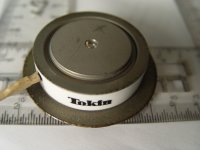
Or go ceramic, 1000W with dual-side cooling. (50 bucks SIT in a power diode package)
Attachments
You might like this one :
http://images.ihscontent.net/vipimages/VipMasterIC/IC/TOKN/TOKND004/TOKND004-1.pdf
http://images.ihscontent.net/vipimages/VipMasterIC/IC/TOKN/TOKND004/TOKND004-1.pdf
Attachments
Back in the mid '80s, the aluminum-oxide insulators for large packages I could obtain, had a 3 to 4.5 mm thickness. Performed worse than mica.
2 decades later Mark Gulbrandsen helped me to some insulators with 2mm thickness. Performed better than mica.
How very odd, that is not consistent with the thermal conductivities of the two materials.
I suspect the surface finish of the thicker Al2O3 was too rough. It is important to have very smooth flat ceramic surfaces otherwise the grease between the package metal and the ceramic will dominate the thermal resistance.
Or go ceramic, 1000W with dual-side cooling. (50 bucks SIT in a power diode package)
That's a cute little unit. What compression level do they require? 1500 psi is industry standard, but my diodes needed 2500 psi, or 9 thousand pounds total force.
To get best use, mount non isolated packages to a copper spreader plate , minimum 3 to 4 mm thick (your welcome Sy) using copper filled grease, and get your ele isolation when that copper is mounted to the aluminum sink. Paralleled devices will also benefit because the copper pad will act more isothermal for multiple devices.
jn
Are you saying there will be no continuity between the copper grease or the copper and the alu? I had all kinds of problems using Arctic Silver ?
No. What I am saying is, use conductive grease between the chip package and the copper heat spreader. Insulate the copper spreader from the aluminum heatsink.
That way, you use the better thermal conductor where the heat flux density is highest.
jn
@ jn - O.K. understood.
@BigE - I suspect my problems came from the squeeze-out at the edges of the pads. Same result if I used mica or elastomeric. I suspect using the copper spreader with sufficient margins and some extra care will work well. I'll try it next time around.
@BigE - I suspect my problems came from the squeeze-out at the edges of the pads. Same result if I used mica or elastomeric. I suspect using the copper spreader with sufficient margins and some extra care will work well. I'll try it next time around.
Is there no chance that the conductive grease will migrate and short the pins of the package?
If the application is careful, and the edge cleaned, I wouldn't worry.
The old school way of blobbing grease on, then squeezing it out with the hardware is definitely not the right way to do it. I'd certainly resist doing that with a conductive grease.
You could always put nail polish on the leads after soldering, to extend the creep path.
jn
Someone around the threads suggested putting the compound on you thumb and forefinger and coating both sides of the insulator at the same time. That puts just enough on and avoids excessive squeeze-out. I've used some throwaway super thin vinyl gloves and it works just fine.
Last edited:
Someone around the threads suggested putting the compound on you thumb and forefinger and coating both sides of the insulator at the same time. That puts just enough on and avoids excessive squeeze-out. I've used some throwaway super thin vinyl gloves and it works just fine.
In my antique clock work, sometimes it is useful to take a little Teflon spray and wipe it on the surfaces using a Q tip after the device has been mounted. The purpose is to break the surface tension of the oils so that wicking cannot occur.
After full mount, wipe excess squeeze-out if any, and then spray Teflon on another Q tip, and wipe it along the case side and heatsink surface.
jn
- Home
- Amplifiers
- Pass Labs
- F5 power amplifier


