I think everything is fine, I am happy. Do I have to build a F4 now?
Yes, of course! Or an Aleph...
on the back side
Remove the nuts between the heatsinks and chassis, and you'll have a real class A amp.
When I first completed my F5 I was comparing it to my Aleph4. I was not too impressed, the sound was to clinical and harsh.
I've just added an Impasse pre-amp into the loop - CD, B1, Impasse then F5.
The Impasse really does round off those unpleasant edges and make it quite pleasant to listen to, much more like the Aleph sound that I have come to love.
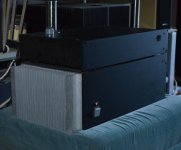
You can just see the mighty Aleph 4 in the background.
This F5 runs surprisingly cool.
I've just added an Impasse pre-amp into the loop - CD, B1, Impasse then F5.
The Impasse really does round off those unpleasant edges and make it quite pleasant to listen to, much more like the Aleph sound that I have come to love.
You can just see the mighty Aleph 4 in the background.
This F5 runs surprisingly cool.
Attachments
Last edited:
When I first completed my F5 I was comparing it to my Aleph4. I was not too impressed, the sound was to clinical and harsh.
.
I too have had the same experience, however I didn't have an Aleph to compare it to. However, I swapped out the stock feedback resistors to Caddock's and replaced the input resistors to Vishay nudes, as well as changed the bias resistors to the Fukushima's that Buzz was GBing, and all that harshness and clinical sound was gone! The F5 became much more musical and engaging to my ears. Also found that biasing higher also resulted in a more effortless sound.
I swapped out the stock feedback resistors to Caddock's and replaced the input resistors to Vishay nudes, as well as changed the bias resistors to the Fukushima's that Buzz was GBing, and all that harshness and clinical sound was gone!
Interesting observation. Thanks for sharing.
Oh No
Well, after my misadventure during building and setting up something eventually failed.
If you remember I made the mistake of setting P1 and P2 to their mid positions at first turn ON.
This resulted in an initial bias of some 4A ISTR.
After correcting the mistake everything then biased up correctly and it's been happily running for about 6 hours or so.
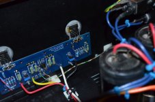
Well, finally one of the MOS-FETs must have failed,. taking its gate stopper in the process.
Nothing else looks cooked but could something else be amiss too ?
Well, after my misadventure during building and setting up something eventually failed.
If you remember I made the mistake of setting P1 and P2 to their mid positions at first turn ON.
This resulted in an initial bias of some 4A ISTR.
After correcting the mistake everything then biased up correctly and it's been happily running for about 6 hours or so.
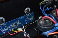
Well, finally one of the MOS-FETs must have failed,. taking its gate stopper in the process.
Nothing else looks cooked but could something else be amiss too ?
Attachments
Maybe the secondary winding of the Jensen [driving the failed MOS-FET] is open. Please ignore my reply; for a second I believed that it was an F6 instead of F5.Well, after my misadventure during building and setting up something eventually failed.
If you remember I made the mistake of setting P1 and P2 to their mid positions at first turn ON.
This resulted in an initial bias of some 4A ISTR.
After correcting the mistake everything then biased up correctly and it's been happily running for about 6 hours or so.
Well, finally one of the MOS-FETs must have failed,. taking its gate stopper in the process.
Nothing else looks cooked but could something else be amiss too ?
Last edited:
Well, after my misadventure during building and setting up something eventually failed.
If you remember I made the mistake of setting P1 and P2 to their mid positions at first turn ON.
This resulted in an initial bias of some 4A ISTR.
After correcting the mistake everything then biased up correctly and it's been happily running for about 6 hours or so.
Well, finally one of the MOS-FETs must have failed,. taking its gate stopper in the process.
Nothing else looks cooked but could something else be amiss too ?
About midway through the first chapter of the Service and Maintenance Manual for the HP-3577A spectrum analyzer there's a paragraph to the effect of: "We know you're not reading this manual for pleasure, that you've encountered a problem with your spectrum analyzer. Most likely this is a result of failing to read the instructions accompanying the analyzer. This is a common fault of engineers..."
... This F5 runs surprisingly cool.
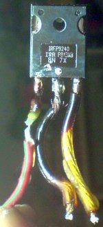
... Well, finally one of the MOS-FETs must have failed,. taking its gate stopper in the process....
Sad old story: poor thermal connection between the MOSFET and the heatsink resulting in cool heatsink and burning MOSFET.
And the story ends like this:
Attachments
K&D,
you're better off by placing a pressure spreader between the mosfet and the screw/bolt head.
A plain washer works, best is a spring disc, or coins with a protruding edge (spring disc effect)
Mounting a power device with just a screw may still be acceptable for class AB (to some), but a high dissipation purpose definitely requires a washer.
If anyone is following the demise of my B&W 683, the F5 died and applied 24V DC to the speaker.
The Midrange and the Tweeter are OK as they are protected by series caps.
When the amp died I was upstairs. Both channels of the F5 share a common power supply and the working channel just kept on working.
The voice coils in the Bass units are both well cooked but have not gone open circuit. The heat generated has caused the coils to come away from the cones so the drivers are goosed.
My question here is do you think the crossover coils will be OK ? Both Bass crossover coils use 1.25mm wire and have probably got a bit warm with the DC flowing through them. As the voice coil wiring is much finer and has not fused I'm assuming that the crossover coils are probably OK.
DC resistance is OK and is identical between the working and non-working speaker. I appreciate that the coils have very low DC resistance anyway.
I can't think of any other way of checking to see that the coils haven't been fried too.
- Home
- Amplifiers
- Pass Labs
- F5 power amplifier