Andrew, you are right, I didnt use a bulb, I ordered a vario trafo.
I certainly feels like a short, but I testet the amp boards separately with up to +/- 15V 0.5A without any issues, and I testet the PSU separately without any problems.
I have only 2 connections to the chassis: A security ground located near the mains input, and a PSU ground. Inputs are floating with a screened wire, and under test i short the input to prevent oscillation.
The next thing I am gonna do is to disconnect the PSU again to se if the diodes died, and then make a bulb thing, and wait for my vario trafo.
Unless I recieve other suggestions.
Best regards
Arthur.
The fuse isn't there to protect the amplifier, it is there to protect against catrastrophic failure - ie FIRE.
I use a 2.5A Slow Blow with a 500VA transformer.
Do use the variac and bulb tester to make sure that everything is working correctly, then spec the fuse to prevent fire. 500VA transformer can draw 2A without any danger of burning but will need a bit more than that for in-rush - hence 2.5A slow blow.
If you want to offer the amps some form of fused protection, you can use 2A fuses in the +/- supply lines. (You might even need 4A fuses)
Last edited:
I just found a bulb thing I made some years ago. I didnt find it much helpfull then and still dont.
The amp can be turned on with the bulb thing, but there is no voltage to speak of on the power supply, so I put in a 1A fuse - which blow up immidiately without the bulb.
I suppose I have lost the diode brigdes again.
And I am afraid that the vario transformer doesnt help me ither. It will work for a short time, and then blow the fuse - and then what ?
This amp make me loose the rest of my already sparringly hair, and turn me from an ampaholic to an alcoholic")
The next thing I will try is to power up one side of the amp with the small power supply, and see if I can get a signal through the circuit.
It reminds me of a problem we had with a Rickenbacker guitar with a passive circuit. Over time we changed and resolderet everything, without getting rid of the problem, and it showed up that there where random disconnections in the PU wirings - on 2 different new PUs.
Statistically that that should be almost impossible.
It seems like a simple circuit, but I am getting out of ideas with this amp.
The amp can be turned on with the bulb thing, but there is no voltage to speak of on the power supply, so I put in a 1A fuse - which blow up immidiately without the bulb.
I suppose I have lost the diode brigdes again.
And I am afraid that the vario transformer doesnt help me ither. It will work for a short time, and then blow the fuse - and then what ?
This amp make me loose the rest of my already sparringly hair, and turn me from an ampaholic to an alcoholic
The next thing I will try is to power up one side of the amp with the small power supply, and see if I can get a signal through the circuit.
It reminds me of a problem we had with a Rickenbacker guitar with a passive circuit. Over time we changed and resolderet everything, without getting rid of the problem, and it showed up that there where random disconnections in the PU wirings - on 2 different new PUs.
Statistically that that should be almost impossible.
It seems like a simple circuit, but I am getting out of ideas with this amp.
Near zero volts at the transformer means full voltage across the bulb. That tells you there is a major fault !!! That's why "bulb ON" = fault condition !!
start by disconnecting all your assemblies.
Add on the transformer alone, test
add on the rectifier, test
add on the smoothing, test
add on ONE amplifier, test
remove that successful amplifier.
add on the other amplifier, test
get the idea?
start by disconnecting all your assemblies.
Add on the transformer alone, test
add on the rectifier, test
add on the smoothing, test
add on ONE amplifier, test
remove that successful amplifier.
add on the other amplifier, test
get the idea?
BTW,
I don't find using a Variac at all useful in helping to prevent damage when there is a fault.
I also don't find it useful in trying to identify the fault. Too many hands required and too many eyes required at the same time.
Whereas the Bulb Tester is automatic. It detects sustained excessive current draw and effectively protects the transformer and all downstream.
The most common error is to have the PSU caps the wrong way round. The second is to have the P and N FETs in the wrong PCB positions.
Something is blowing your rectifiers......?
The power MOS-FETs are easily damaged by static discharge but, you only need to use reasonable care here, not clinical ESD environment.
Something is blowing your rectifiers......?
The power MOS-FETs are easily damaged by static discharge but, you only need to use reasonable care here, not clinical ESD environment.
Last edited:
Thanks a lot everybody,
I really appriciate your input, og I will try the testing scheme from Andrew - and yes I get the idea
Actually I did something like it, I tested the amps separately and the PSU separately, but when I connected them together it didnt work. I will now try to test one amp with an external PSU, and see if I can get signal through, because I still suspect that there must be a severe failure in the amp boards.
A little bit sorry that I ordered the vario transformer, but I could use it to start up my tube amps gracefully.
The Variac will come in very useful later.
I have two principle uses.
a.) to check transformer outputs over the full range of mains voltage from 216Vac to 254Vac. Many transformer get very near saturation at 254Vac.
b.) to create a controllable DC supply independent from my 3channel lab supply.
I have a 100VA, EI, 240:12+12Vac permanently wired to the Variac output. The AC output is with 4 off 4mm banana sockets.
I can then plug in a rectifier/smoother and it allows from +-0.5Vdc to +-18Vdc at a turn of the knob. or from +0.5Vdc to +36Vdc.
I also have the Bulb Tester wired into this same "tester" box.
I have taken some pictures to document my amp, but found out that it is not possible just to attach pictures.
It seems that I need an URL somewhere to do that - a little bit inconvinient, but I suppose it is to save space on the DIYAudio web server.
Everything is underlined when I write my messages, I thought I could write a close to understandable English
It seems that I need an URL somewhere to do that - a little bit inconvinient, but I suppose it is to save space on the DIYAudio web server.
Everything is underlined when I write my messages, I thought I could write a close to understandable English
It seems I had to choose advanced editing, which I were not aware of.
Wonder if it works this time.
Wonder if it works this time.
Attachments
I can see that I should have credited Pass on the faceplate, but rigtht now he wouldnt be proud of me
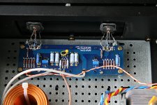
I use 2 trafos because I originally wanted to do 2 separate PSU´s, but I didnt find the space sufficient.
The screw terminals are to isolate the power supply.
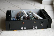
On picture 3 you can see the 2 chassis connections. On the left the mains earth, and in the middle the PS earth.
I use 2 trafos because I originally wanted to do 2 separate PSU´s, but I didnt find the space sufficient.
The screw terminals are to isolate the power supply.
On picture 3 you can see the 2 chassis connections. On the left the mains earth, and in the middle the PS earth.
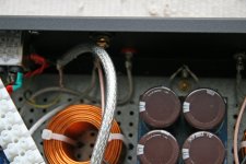
Could a stray wire from the mains shield be shorting the mains? The picture makes it look close to the connections at the transformer end. With good twisting of the wires you don't need to be so aggressive shielding. A bit of heat shrink on the ends of the connections would keep the ends of the braid under control.
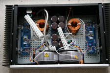
I like your home-made fender washers on the output devices.
Double check that you have the transformer windings connected correctly - are they anti parallel causing a short? When you get to the check the rectifiers stage, try one winding at a time.
I like your home-made fender washers on the output devices.
Double check that you have the transformer windings connected correctly - are they anti parallel causing a short? When you get to the check the rectifiers stage, try one winding at a time.
Last edited:
The shielding does not touch anything, but I have put some isolation tape on now. It is of course not a silly question, but I do have isolation washers on all the MOS FETS. But when I measure from ground to the MOS FET pins I get different readings on the amp 2 sides.
One side shows about 18Kohms from all 3 pins to ground, (I think that that was on the channel that I connected last time) and the other side shows indefinte on all pins? Maybe that could be the problem, but what is the course?
The home made Fender washers are Danish Crowners They are not good for much more than this
I think I have the windings correctly connected, in that when I the last time tested the PSU without a load it worked correctly.
But when I connected the amp board the diode bridges died.
One side shows about 18Kohms from all 3 pins to ground, (I think that that was on the channel that I connected last time) and the other side shows indefinte on all pins? Maybe that could be the problem, but what is the course?
The home made Fender washers are Danish Crowners
They are not good for much more than this I think I have the windings correctly connected, in that when I the last time tested the PSU without a load it worked correctly.
But when I connected the amp board the diode bridges died.
But when I connected the amp board the diode bridges died.
Logically then, you might want to connect the channel boards without the
outputs attached.
- Home
- Amplifiers
- Pass Labs
- F5 power amplifier