Over time I have run into examples of DIY F5's that were marginally stable
or perhaps a bit twitchy on the top end.
My own observations of the top end of the F5 with some of the full range
drivers was that it was a bit like "putting instant coffee in a microwave oven"
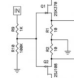
I went back to that recently and found that increasing the value of the 1K
input resistor to as high as 4.7K helps this, and recommend that people
experiencing overly bright sound or instability try it.
The resistance forms a low pass filter the input capacitance of the Jfets, and
takes the bandwidth down from the 1 megahertz region.

Hi Nelson,
Thanks for that explanation. Did you increase the mosfet gate resistors for the same reason?
Also of note, in the first F5 schematic the 100K ground reference resistor was placed after the 1K input resistor, while in later versions the ground reference was placed in front (as well as changed to 47K). Can you comment on the advantage (if any) of that change?
Attachments
comment is already there - you quoted it
Nelson said why the input resistor value was changed, but didn't say why he changed the configuration of the resistors.
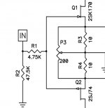
There are other differences in the F5 V2 schematic besides R9:
R10 is 47.5k
R10 R20 are 100R
R22 22 are 10K
R13 R11 are 100R
I wonder if it's worth changing all of them? I didn't realize there were two versions until I looked up R9.
Additionally P3 pot was added and TH1 and TH2 don't go to the rails. I'm wondering if there will be new boards available which reflect all the changes to the circuit?
comment is already there - you quoted it
Hi ZM,
After puzzling over your meaning, the only thing I can think of is that if the ground reference resistor is after the input resistor then it no longer forms an R-C [input R - JFet C] low pass filter?
And what problem is it you have with us girls liking electronics too. Now you can see why I hide behind my dads identity.
Firstly, thanks for the admission on the use of the one account.
The big problem is it that it gets confusing... I've sometimes felt in some threads that "surely K&D knows that without even asking". Two, possibly three of you posting under one account... well you see the problem.
... changed the configuration of the resistors.
Additionally P3 pot was added and TH1 and TH2 don't go to the rails. I'm wondering if there will be new boards available which reflect all the changes to the circuit?
Which of these changes are implemented in the boards currently available
from the store ? All / none /some ?
(P3 seems to be missing, how about the thermistor position ?)
Last edited:
The boards from the store's last batch include P3 right next to the input jfets and the thermistors connect between Q5 Source and R12 as shown in the article. Not sure when this was incorporated.
Still shows Rev. 2.0 in the store?
My output boards are V3.0, front end V2.2. I guess Jason needs to update the store's page.
The F5 is only one board. Are you referring to the turbo boards?
Today I finally hooked up the amplifier boards to the power supply. Biased both channels without any problems. I kept them powered for an hour or so and re-adjusted the bias. That's when I noticed the transformer humming a bit. I tried swapping hot and cold because that was the easiest thing to try. Any ideas how to get rid of it? I'm using a 300W (Amplimo) transformer. Maybe the F5 is just a bit too much for a 300W transformer, because there was no audible hum when I had just one channel connected.
Last edited:
Today I finally hooked up the amplifier boards to the power supply. Biased both channels without any problems. I kept them powered for an hour or so and re-adjusted the bias. That's when I noticed the transformer humming a bit. I tried swapping hot and cold because that was the easiest thing to try. Any ideas how to get rid of it? I'm using a 300W (Amplimo) transformer. Maybe the F5 is just a bit too much for a 300W transformer, because there was no audible hum when I had just one channel connected.
Probably DC in your mains 230V....
I had the same problem with Amplimo transformers. Read this: Mains DC and Transformers
I build figure 8 in a separate box and no more hum.
Walter
Hello again,
I'm slowly starting to develop the project of building a F5 in my head. I've already come across several problems, some of which I can't seem to solve by reading up on them. I've read the article about grounding by Dave Davenport and did not quite get it. I have huge problems understanding his diagrams.
I understand that for satefy reasons I have to connect the chassis to earth. I've planned on using the schematics for the "First Watt PS 0 R1 Power Supply" which is found in the F5 pdf. Why is the power ground connected to earth and why is a thermistor between them? How do I connect the grounds of the amplifier circuit and the input signal to that ground - a simple wire? I want to have the PS and amp in seperate boxes and since the thermistor between earth/chassis and ground seems to indicate a potential difference between the two I'm wondering if i need to connect both ground and earth with 2 seperate wires to the 2nd box, one going to the chassis and the other going to the ground of the amp circuit.
- Home
- Amplifiers
- Pass Labs
- F5 power amplifier