Assembly is screw->bolt->washer->mosfet->silicon paste->mica sheet->silicon paste->heatsink.
Can put my hand on heatsink for minutes but 5 seconds on washer is uncomfortable.
I do have Berquist Silpads (TO220) but they seem to be undersized for Mosfets. My understanding is if using Silpads then thermal paste is not necessary?
Probably all know this but...
Maybe be worth thinking as the transfer of heath as if it was a resistance.
If the thermal resistance betwe mosfet and sink is hi one end up with coll sink and very hot mosfets this is not good for the mosfets.
Sill pads are IMO (and many others) unreliable Papa likes Mica and gopp
I and many others use Kerafoll 86/83.
Any chance you can mesure the temperature of the mosfet Junction?
Best place is the Drain leg as close as possible to the mosfet body and then work out junction themperature with the graphs on the data sheet.
A PT100 probe wuld do nicely
Also realy worth ones time from ESP again realy precious guide lines
http://sound.westhost.com/heatsinks.htm
Last edited:
I use something like this:
Amazon.com: HDE Temperature Gun Infrared Thermometer w/ Laser Sight: Home Improvement
Amazon.com: HDE Temperature Gun Infrared Thermometer w/ Laser Sight: Home Improvement
I use something like this:
Amazon.com: HDE Temperature Gun Infrared Thermometer w/ Laser Sight: Home Improvement
Sorry but that won't work.
cek the size of the focusing spot and how well it deals with shiny surfaces.
prety good for many other things ....
Laser sight is there for same reason apart fron scaring wife and kids.
a 2 x1 mm PT100 is the thing and cost about £1.5 plus capable DM or same math and boiling water to draw the curves.
Do not trust what I say just look at distance to spot ratio and work it out.
Last edited:
Unfortunately what is easily available in the West is not available in India :-(.....that said I'll get the mica insulation pads from digikey & try them out...we do have a local goop called Anabond & that works well. I do follow the ESP method of applying heat sink compound
I have a source for thin & small anodised aluminium sheet maybe try them out also
It is good that this one channel is a sort of Proof of Concept") ...final channels will be built with fresh boards & components
...final channels will be built with fresh boards & components
I have a source for thin & small anodised aluminium sheet maybe try them out also
It is good that this one channel is a sort of Proof of Concept
...final channels will be built with fresh boards & componentsYou'll be fine with mica; 3 conditions:
- your contact surfaces must be lapped - flat and shiny. No surface abrasions, screw hole edges must be de-burred!
- as little of thermal paste as possible; basically, so thin that it's almost completely transparent
- most importantly, enough of EVEN pressure across the FET surface. A piece of alu-bar across the FET (a "cross-bar") with screws on both sides does miracles. See how bksabath mounts his output devices to the HS.
Hot washer and warm HS are the symptoms of premature FET death.
Most IR camera's and sensors don't pick up on metal surfaces properly. The emissivity index is totally different for shinny metal sufaces(they will actually look cold when they are 55C!). You can get around this by applying "white-out" typewriter correction fluid in a thin layer. I use Ceramique, a white colored, Arctic Silver goop made of 3 or 4 or 5 different sized tiny ceramic balls in a solution, for maximum cunducting of radiaded temperature. Not Arctic Silver 5, Arctic Silver "Ceramique". The IR camera will read proper temp with a thin layer on the device. The thin layer will efficiently conduct the temp throuout the substance.
The emissivity index of black plastic as used on TO-247 etc. is .96. Almost no need to change anything, you can probably get accurate enough measurements looking directly at the plastic.
The emissivity index of black plastic as used on TO-247 etc. is .96. Almost no need to change anything, you can probably get accurate enough measurements looking directly at the plastic.
Thank you gentlemen...visual plastic inspection went ok
Glad we saved the life of those poor mosfets. as you say that now sink is noticebly warmer they must have been roasting (compare size of mosfet with size of sink)
To be constructive and help others the question remain.
So what is the temperature at the drain leg?
Drain leg is just metal extension of the metal substrate that get heat from the Junction so it present the least thermal resistance to it (other best place wuld be the metal back but that is on the sink so no dice)
DM-315 - LABFACILITY - SENSOR, PT100, THIN FILM, 1.2X1 | Farnell United Kingdom
This is similar to the one I use (real pain to solder as is just 1.2 X 1.6 mm)ad a capable DM at £20 may not be posh but at least one know where is taking the reading.
I will try to post picture of my set up tomorow.
One of my DMM has a temperature measure with K type input....let me try to get hold of a comparable lead for contact measurement
K thermocouple even more precise than PT 100 and extended themperature range and faster response.
5 minutes of work for piece of mind.... priceless
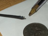
And picture of PT100 (crappy macro mode on camera) but give you idea of how precise one can be in regard to where temperature is taken.
Attachments
psu
If i dont use TH1 in the PSU do i just connect GND to the chassis ?
also i dont have a variac to bring up the voltage, i tested the amp with 2x 9v batterys just to see and it makes sound so im thinking of just hooking up the +&- 24v and hoping it works fine mesuring then quickly turning off, i just want to be safe realy, i have a light bulb in series with the primary transformer winding.
Im building this for a friend, if it was for me i wouldnt mind blowing anything up lol
Yes, just connect to chassis. If you have ground loop hum, you can always try adding TH1 to see if that solves the issue.
In my experience, the bulb tester was enough to keep things from blowing up until you confirm things are ok. I also kept an eye on my DMM measuring bias to know if I needed to adjust the pots in the opposite direction that I had assumed would provide zero bias.
In my experience, the bulb tester was enough to keep things from blowing up until you confirm things are ok. I also kept an eye on my DMM measuring bias to know if I needed to adjust the pots in the opposite direction that I had assumed would provide zero bias.
If i dont use TH1 in the PSU do i just connect GND to the chassis ?
also i dont have a variac to bring up the voltage, i tested the amp with 2x 9v batterys just to see and it makes sound so im thinking of just hooking up the +&- 24v and hoping it works fine mesuring then quickly turning off, i just want to be safe realy, i have a light bulb in series with the primary transformer winding.
Im building this for a friend, if it was for me i wouldnt mind blowing anything up lol
Thankyou, seemed to work great, i had it all biased up to around 4v all going well then i turned it off and put the bias back to zero because i wanted to take the light bulb out and start again biasing up both channels, anyway something strange has happened i dont know if perhaps if P1 has been damaged but when i measure across r3 i get no measurement on the DMM, where on all the other p1 and p2,s i can get close to 0-2 ohms.
il check if ive turned that pot the wrong way tho! lol
il check if ive turned that pot the wrong way tho! lol
Thankyou, seemed to work great, i had it all biased up to around 4v all going well then i turned it off and put the bias back to zero because i wanted to take the light bulb out and start again biasing up both channels, anyway something strange has happened i dont know if perhaps if P1 has been damaged but when i measure across r3 i get no measurement on the DMM, where on all the other p1 and p2,s i can get close to 0-2 ohms.
il check if ive turned that pot the wrong way tho! lol
haha and you know what, i did turn it the wrong way! word of caution to people ! i love to double check things thise days or else it could become not pretty!
4V or 400mV?
4v not mV. across R3 amd R4
less than 0.6v across r12 and r11, but im still tweaking!.....
4v not mV. across R3 amd R4
less than 0.6v across r12 and r11, but im still tweaking!.....
Ah, I misread and thought you were talking about R11/12 since you said you had them biased to 4V. Is there a reason to measure voltage across R3 and R4? I only checked resistance to verify the pot position.
Also, re: thermal compound, I would use it for the mica pads. You want the sinks to be as smooth as possible AND use thermal compound to reduce the thermal resistance from the body of the MOSFET. Is it absolutely necessary? Probably depends on how big your sinks are, ambient temp, etc. But it can only improve the reliability and long term life span of those MOSFETs.
My 2 cents.
- Home
- Amplifiers
- Pass Labs
- F5 power amplifier