there is nothing wrong with adopting a different output bias for the F5.Hello all. I have a question most of you probably will laugh at but anyway: what is the penalty of biasing the F5 at lower current ? For instance 0.5 A.
The F5 is a Push-Pull ClassA amplifier that automatically transitions over to ClassAB if the peak current demanded by the load exceeds the ClassA limit
This change from ClassA to ClassAB will happen no matter what bias you set up. The bias current simply sets the limiting ClassA current capability.
Hello all. I have a question most of you probably will laugh at but anyway: what is the penalty of biasing the F5 at lower current ? For instance 0.5 A.
Hi Jean-Paul,
at this time I'm thinking about the same thing.
Anywhere, several months ago, I read here in the forum that you should not go below 0,7A bias with the IRF Parts, as far as I remember this was posted by ZM. But I can't find the post any more and I can't remember the reason. An issue with the input capacitance that rises at lower bias levels?
If we knew the reason it would be interesting if the 2sk1530/2sj201 have the same problem with "lower" bias values.
I am thinking about 0,5A-0,7A what would be sufficient for my normal listening levels.
I am a litte careful with the increasing distortion because I an thinking about increasing the gain by lowering the feedback too. Both mods could be to much as I like the original F5 that a friend of mine uses.
Best regards
Flo
Last edited:
......it will not be run at high volume anyway.
how about lowering supply voltage a bit, as well ?
you might even be able to use regulated supply, and be able to adjust voltage
You can do all these things, the only penalty is higher distortion in the case
of the bias, and higher distortion and lower power in the case of lowering
the rails. The distortion is already fantastically low for such a simple amplifier,
so you have some margin to do that.
😎
of the bias, and higher distortion and lower power in the case of lowering
the rails. The distortion is already fantastically low for such a simple amplifier,
so you have some margin to do that.
😎
You can do all these things, the only penalty is higher distortion in the case
of the bias, and higher distortion and lower power in the case of lowering
the rails. The distortion is already fantastically low for such a simple amplifier,
so you have some margin to do that.
😎
Thank you for the answer Nelson,
will give it a try and report when I'm finished with the amp, the "living room capable F5".
Regards
Flo
He could be a student, and regularly listens to a remix of The Police : Living in a Closet.
(a hundred billion castaways, looking for a home)
(a hundred billion castaways, looking for a home)
Last edited:
Is the original one not "living room capable" ?
Not compatible with my living room which is shared with several girls (wife and three doughters). Main issues are energy consumption, placement and according ventilation, size of the enclosure, usability for all the family etc,. There are always compromises...
But I have my own room too where those factors do not count 🙂
He could be a student, and regularly listens to a remix of The Police : Living in a Closet.
(a hundred billion castaways, looking for a home)
Sorry I'm not, finished my studies more than a decade ago. There are other reasons, compromises etc. in my other room a Mini-J is delivering the physical and mental heat.
But I think my circumstances are note the topic here...
Yes of course, thanks for the hint. I have things like that on my testbench.
The advantage of the F5 over a lot of other proposals is the freedom to choose between class A and class AB with the bias dsired/needed. I like the idea to have power if needed (to be honest I am thinking of a higher supply voltage) and to have the first couples of watts in class A quality.
That's my reason to build one for the living room. The intention of my question above was to get statements on the lowest reasonable bias. Now I can plan further, determin the power I need in times of serious listening, determin the power needed for really loud listening and choose the apropriate voltage and bias.
Best regards
Flo
You can do all these things, the only penalty is higher distortion in the case
of the bias, and higher distortion and lower power in the case of lowering
the rails. The distortion is already fantastically low for such a simple amplifier,
so you have some margin to do that.
😎
Thank Mr Nelson Pass! i like this amp much, I want to buy it but difficult (far from ..) so try to make it.
for your answer you mean if the rails good, class A will depend on correctly bias value & material , if higher or lower it will not perfect .
going to purchase mains filter cap from manual power supply schematic .0033
can you please recomend me some better type for 230Vac
can you please recomend me some better type for 230Vac
going to purchase mains filter cap from manual power supply schematic .0033
can you please recomend me some better type for 230Vac
Read this piece from Kemet on selection of X and Y capacitors:
http://www.kemet.com/kemet/web/home...ege Presentations/$file/EvoxRifaRFIandSMD.pdf
Not necessary that you use Kemet --just some good info.
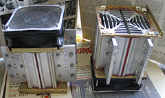
Oh look, shiny new F5 Turbo pc boards have arrived!
You will be able to run a lower bias and still melt stuff.
😎
You will be able to run a lower bias and still melt stuff.
😎
Gotta build a few before the parts values are nailed down. For some reason
the prototype parts are always spot on. Production runs put the lie to the
original schematic. Look for it around Xmas.

the prototype parts are always spot on. Production runs put the lie to the
original schematic. Look for it around Xmas.
Gotta build a few before the parts values are nailed down. For some reason the prototype parts are always spot on. Production runs put the lie to the original schematic. Look for it around Xmas.
Thanks Santa! I'll try and stop drooling while I wait... 🙂
For some reason
the prototype parts are always spot on. Production runs put the lie to the
original schematic.
Hmmm, same thing happens in software now that I think of it. Must be some deeper, underlying principle at work....
So a slightly improved F5 (Turbo) or you could say Rev B is being worked on? Keep me posted for boards. I want to build one!
- Home
- Amplifiers
- Pass Labs
- F5 power amplifier