For a truely versatile curve tracer, you need to be able to vary the DC offset as well as the AC amplitude, preferrably by the computer. I already assume you are willing to add whatever hardware necesarily for that. Then you also need to have a means of figuring out the DC level that exists before the soundcard DAC. By the time you have done all that and interfaced it to the PC, you might as well build a curve tracer from scratch.
Elektor has a kit for small signal stuff which will do quite a lot.
http://www.elektor.com/magazines/2009/february/transistor-curve-tracer.810360.lynkx
It is measuring high current stuff over long period of time without dift (for power device matching) that is the difficult bit. Can be done. Just cost moeny and effort.
Patrick
Last edited:
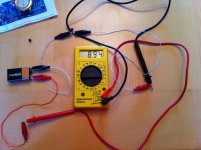
look at post 11251.Using the method 6L6 supplied, I get 9.15 volts (new 9V batt voltage)... which I'm guessing means they are bad and I need new ones.
erpiii
you have omitted the resistor.
That resistor is there to allow you to measure the Vdrop across the resistor and that in turn allows you to calculate the current. In this case Idss current.
As said a little earlier, don't use a 1k0 with a 9V battery. Try 10r.
A 199.9mVdc scale on a DMM will allow a measurable current range through the 10r of 0.02mA to 19.9mA. That is sufficient to measure any gr or bl grade of k170 and will also measure most v grade.
You can use the same jig, with the same resistor, to measure j74. But one must reverse the battery connections to suit the Pchannel jFET.
This is a PASS designed project.
The PASS site shows all this and more.
You need to research your F5 project. Don't expect to be spoon fed !
Last edited:
I have been playing quite a lot lately with matching Idss. I find that DMM drift and ambient temperature are the problems.(or two aspect of the same problem). You can work a bit around them, with a two round measurement. First you measure the devices as they come out of the bag, and put apart the potential matches. Then you measure again the potential matches in sequence, so that between measure of the items passes a very short time. I normally let them stay until in the measurement set until the measure is stable. Normally I do this while doing something else, so I often forgot them in the measurement set for long.
D.
D.
Davide,
If you DMM drifts, then you should get one that doesn't.")
What I do is to set aside one particular FET that I measured 5 minutes after warming up all equipment. Note the value, and then measure it again every 10 minutes to make sure I get the same reading again. And of course you always have to allow minutes for the reading to settle.
But you probably don't have to be so fuzzy about matching as I do.
Probably won't hear any difference.
Patrick
If you DMM drifts, then you should get one that doesn't.
What I do is to set aside one particular FET that I measured 5 minutes after warming up all equipment. Note the value, and then measure it again every 10 minutes to make sure I get the same reading again. And of course you always have to allow minutes for the reading to settle.
But you probably don't have to be so fuzzy about matching as I do.
Probably won't hear any difference.
Patrick
This is getting sidetracked into an issue of JFET measuring. Here's the device which Erno Borbely described in his Audio Electronics (5/99) series of articles "JFETs the New Frontier":
Regrettably, Erno seems to have taken his site down. So:
1) In position 1, 10uA is fed into the source, this gives you the pinch voltage Vp.
2) positions 2 and 3 give you Vgs for currents of 2mA and 5mA.
3) position 4 gives you Idss.
gm= -(2 * Idss/Vp)*[1-(Vgs/Vp)]
You have to switch the batteries for P-Channel devices.
An externally hosted image should be here but it was not working when we last tested it.
Regrettably, Erno seems to have taken his site down. So:
1) In position 1, 10uA is fed into the source, this gives you the pinch voltage Vp.
2) positions 2 and 3 give you Vgs for currents of 2mA and 5mA.
3) position 4 gives you Idss.
gm= -(2 * Idss/Vp)*[1-(Vgs/Vp)]
You have to switch the batteries for P-Channel devices.
Using the method 6L6 supplied, I get 9.15 volts
Because your meter needs to be set to milliamps.
If your meter does not have that setting, then you need to add the resistor to the circuit, and read the voltage across it, to then compute the current draw.
Last edited:
if he switches to ammeter function, can you be sure he won't blow up his meter?Because your meter needs to be set to milliamps.
if he switches to ammeter function, can you be sure he won't blow up his meter?
Well, no, as I don't have any idea how careful he is with shorting the leads.
if you measure and match a pair to exact same idss, with any number of digits, the expected variation would be max 0.1ma, in working conditions
now, if you have a pair with one blown, and measure a new one to the exact same idss, with any number of digtis, the max idss variation could be 0.3ma, in working conditions
but if you have a highly controlled test lab, maybe...
but its really great stuff you guys are posting here
very educational
never mind bending the spoon a bit
Because your meter needs to be set to milliamps.
If your meter does not have that setting, then you need to add the resistor to the circuit, and read the voltage across it, to then compute the current draw.
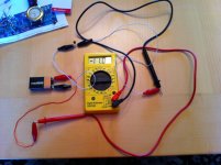
I got a meter the guy said wold read ma. These are the readings I got. Are they correct or do I need to get new ones?
erpiii
Attachments
try measuring across a 100r resistor and see what you get .
To measure voltage or ma?
Mr. Pass himself gave out about 12 of these chassis at the Burning Amp but anodized black.
He gave me a pair (!) with mono inputs, which I can finally build now that he has developed the BA-3 front end, and has posted how to wire it in balanced mode!
http://www.diyaudio.com/forums/pass-labs/201281-burning-amp-ba-3b-balanced.html
Someone asked what the dimensions are, and I carefully measured one and posted the info somewhere..
Given away by?
Mr. Pass or some other person.
Don't think I have seen that one before... not sure why I did not come up with it, but it may be that the extrusions in that shape are actually fairly expensive compared to some others and other solutions...
Would like to give credit.
_-_-bear
Last edited:
For a truely versatile curve tracer, you need to be able to vary the DC offset as well as the AC amplitude, preferrably by the computer. I already assume you are willing to add whatever hardware necesarily for that. Then you also need to have a means of figuring out the DC level that exists before the soundcard DAC. By the time you have done all that and interfaced it to the PC, you might as well build a curve tracer from scratch.
Elektor has a kit for small signal stuff which will do quite a lot.
Transistor Curve Tracer - ELEKTOR.com | Electronics: Microcontrollers Embedded Audio Digital Analogue Test Measurement
It is measuring high current stuff over long period of time without dift (for power device matching) that is the difficult bit. Can be done. Just cost moeny and effort.
Patrick
Maybe it's at least worth thinking about.
There are many good instrumentation adc's available and using sensible parts should ensure decent long term stability. I would think with some care temperature variations between measurement instants would give rise to larger discrepancies.
It would be fun to device an architecture for a curve tracer.
How about a small voltage controllable boost converter to charge a small capacitance. Even 1000uf capacitance should be enough for even 10A pulses if they are short enough (<100us) But then again if VDS / VCE is sampled at the same instant as the Source/Collector current maybe the pulse shape is not that important an even smaller capacitance should suffice.
Making it floating both current measurements and negative voltages can be generated quite conveniently without having two supplies. since depletion mode parts like negative gate voltages it just easy to have the gate driver centered around ground.
But short pulse durations puts some demands both on the ADC's (conversion time) and on the gate driver (available current). I think I'll look in to it and see if maybe i can come up with something sensible and start a thread for it.
Last edited:
It is well known that we are designing and building one (USB Curve Tracer).
Just too many projects and too little time .....
Patrick
I was not aware. In which state is it ?
- Home
- Amplifiers
- Pass Labs
- F5 power amplifier