Hello,
I'm building a F% and was wondering about preamplification. My speakers sensitivity is 90db but their woofer is amplified (Infinity Intermezzo 2.6) so it's just the tweeter being driven.
Would a B1 buffer do the job, or would someone recommend a preamp with gain given 90db sensitivity? Alternatively can the b1 be modifiedfor gain?
Thanks,
Apparently the pumpkin is the fave
I was going to build one 2 weeks ago if I could get the bits for it.
Apart for my usualy poor taste jokes I would suggest that you have a browse
if you can get one it does all and more than needed (single ended and balanced in out in out enough gain for the F4 and the dude that designed the thing is quite nice and helpfull (which is the main thing IMO) when he is not abroad burning sausages) and apparently it sounds preaty good as well.
May even be more than ideal as you could mod the thing for more outputs and what not
Hello,
I'm building a F% and was wondering about preamplification. My speakers sensitivity is 90db but their woofer is amplified (Infinity Intermezzo 2.6) so it's just the tweeter being driven.
Would a B1 buffer do the job, or would someone recommend a preamp with gain given 90db sensitivity? Alternatively can the b1 be modifiedfor gain?
Thanks,
B1;DCB1 or an LDR based pre like George Strancheff's Lightspeed all work well with the F5. I use PMC's which are 90db's and go plenty loud.
After playing flawlessly for over a year, one of the channels has developed a problem. The voltage across the output(r11/r12) has dropped to about 250 mv and the offset is about 175mv. The other one is steady around 580mV and 0 offset. The bad channel still plays but with audible distortion.
Most likely a dirty pot wiper.

Extra follower transistors on F5?
Greetings all,
First off, thanks to everyone (particularly Mr. Pass) for all the fine work/information on this forum.
I'm preparing to build an F5 variant to use with my 4 Ohm full-range speakers (down to 20 Hz), and while I have a bit of electronics experience, I'm not an analog or speaker expert by any means.
Basically I'm thinking of building either an F5 with at least 1 extra pair of follower power transistors to match the 4 Ohm impedance better (i.e. 2 IRFP240/IRFP9240 pairs), or even a balanced F5 with say 3-4 IRFP240/IRFP9240 pairs on each half of the balanced set (so 6-8 pairs total) since it doubles down on the current draw for the same speaker impedance. Contemplating the extra power from the balanced version due to the bass going so low on my speakers.
All this brings up the following question(s) though: Assuming the power transistors are pretty well matched (say 0.5% or somewhat better), does increasing the number of transistors typically:
I.e. building the design with the minimum number of follower transistors is the how to get the purest signal out of it ?
Greetings all,
First off, thanks to everyone (particularly Mr. Pass) for all the fine work/information on this forum.
I'm preparing to build an F5 variant to use with my 4 Ohm full-range speakers (down to 20 Hz), and while I have a bit of electronics experience, I'm not an analog or speaker expert by any means.
Basically I'm thinking of building either an F5 with at least 1 extra pair of follower power transistors to match the 4 Ohm impedance better (i.e. 2 IRFP240/IRFP9240 pairs), or even a balanced F5 with say 3-4 IRFP240/IRFP9240 pairs on each half of the balanced set (so 6-8 pairs total) since it doubles down on the current draw for the same speaker impedance. Contemplating the extra power from the balanced version due to the bass going so low on my speakers.
All this brings up the following question(s) though: Assuming the power transistors are pretty well matched (say 0.5% or somewhat better), does increasing the number of transistors typically:
- Increase the Distortion non-trivially?
- Decrease the distortion into lower impedance loads? (ex: does doubling the transistors make the 4 Ohm distortion similar to the 8 Ohm distortion, modulo errors from matching issues?)
- Do the extra transistors cause more high-frequency distortion due to the extra capacitance now in the follower circuit?
- What does this do to the damping factor, which IIRC is roughly 60 on a standard F5 design?
I.e. building the design with the minimum number of follower transistors is the how to get the purest signal out of it ?
too much fuss
you didn't read even beginning of "official" F5 thread ..... just because those outputs aren't working in follower mode
there are floating in few threads several schmtcs with doubled outputs
I'm perhaps using the wrong terminology by saying "follower"... I'm going to assume "doubled/quad outputs" are the right term for the moment. I have seen several designs here and was not asking about the designs per se, it seems clear HOW to add extra output transistors.
I was asking those experienced ones what the effect of the doubled/quad outputs would have to the resulting audio.
Paralleling output devices will change the measured performance in various
ways. One thing it will usually do is increase the open loop gain, and the
other is that it will make it slower. Assuming that these do not cause some
instability (and modifying an F5 you have to watch out for that), there are
some general rules for how the sound changes.
The spectral balance between bass and treble will alter. The amp will seem
to have more bass and more power and control in the bass region. The
treble will recede a bit, and the overall tone of the amplifier will get darker.
This is not necessarily a bad thing. Usually there is a "best" balance between
light and dark, as with the Alephs. The 3 was a bit shiny, the 1.2 was
comparatively dark. For me, the 2 was just right.
The stock F5 circuit is a little shiny. Paralleling up outputs might help your
perception of the amplifier.
Also, the use of different outputs, in your case, the IRFP9240 will
substantially alter the tone. Again, you may prefer it - some people do.
Paralleling output devices will change the measured performance in various
ways. One thing it will usually do is increase the open loop gain, and the
other is that it will make it slower. Assuming that these do not cause some
instability (and modifying an F5 you have to watch out for that), there are
some general rules for how the sound changes.
The spectral balance between bass and treble will alter. The amp will seem
to have more bass and more power and control in the bass region. The
treble will recede a bit, and the overall tone of the amplifier will get darker.
This is not necessarily a bad thing. Usually there is a "best" balance between
light and dark, as with the Alephs. The 3 was a bit shiny, the 1.2 was
comparatively dark. For me, the 2 was just right.
The stock F5 circuit is a little shiny. Paralleling up outputs might help your
perception of the amplifier.
Also, the use of different outputs, in your case, the IRFP9240 will
substantially alter the tone. Again, you may prefer it - some people do.
Thanks for the info, that will help.
When you talk about "using the IRFP9240 will substantially alter the tone"... are you referring to your selection of having used a "comparable" part of the Fairchild FQA12P20 and FQA19N20C (even though your circuit diagrams all specify IRFP240/IRFP9240) ? Or, is this something else I'm failing to understand?
...
Also, the use of different outputs, in your case, the IRFP9240 will
substantially alter the tone. Again, you may prefer it - some people do.
Thanks for the heads-up on this point!
I found the comments on the forum about output transistor choice and distortion. I'm a detail-nut (that's why I want an F5 derivative in the first place), so I'll probably try out either the Fairchild or Toshiba parts mentioned.
Hasn't this been around?
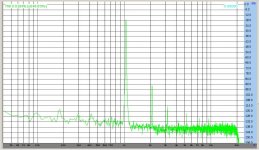
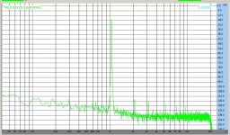
I finally added P3 as shown in post #10856 to my F5 channels which use Cviller V1.1 boards and matched Toshiba 2SK1530 and 2SJ201 MOSFETs. Left channel THD at 1 watt was reduced from .0077% to .0015%. Right channel THD at 1 watt was reduced from .018% to .0012%. WOW, what an improvement with such a small modification!
Attachments

Hi Ihquam
Sorry if out of topic
Are screen shot from Virtinis + Audiohile 192?
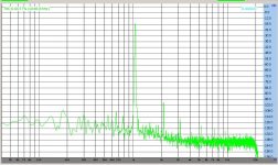
Tried mine again and got similar peack on 200hZ but at -80dB (left most picture)
Made shure conections are fine 3 4 times most probably I got noise going in troug mother board.
I tried the P3 a while ago and burnt a cople of Jfets but now seiing this I worth having a second pop at it
Tanks for posting
Sorry if out of topic
Are screen shot from Virtinis + Audiohile 192?
Tried mine again and got similar peack on 200hZ but at -80dB (left most picture)
Made shure conections are fine 3 4 times most probably I got noise going in troug mother board.
I tried the P3 a while ago and burnt a cople of Jfets but now seiing this I worth having a second pop at it
Tanks for posting
Bksabath:
The screen shots are from Sillanumsoft Visual Analyser with the M-Audio AP-192 sound card.
There should be be problem with adding P3, but be sure to turn P1 and P2 counter-clockwise to reduce the bias currents before turning on the amplifier. Make sure that P3 is adjusted at mid-position of 100 ohms. Then turn on the amplifier and adjust P1 and P2 as described in the "F5 Manual". Finally, adjust P3 to minimise distortion.
I finally added P3 as shown in post #10856 to my F5 channels which use Cviller V1.1 boards and matched Toshiba 2SK1530 and 2SJ201 MOSFETs. Left channel THD at 1 watt was reduced from .0077% to .0015%. Right channel THD at 1 watt was reduced from .018% to .0012%. WOW, what an improvement with such a small modification!
I see you're giving those mosfets a nice workout...thanks for posting your test results. That's a great objective improvement for a simple add-on...any before and after subjective impressions?
WOW, what an improvement with such a small modification!
Did it sound better?
Did it sound better?
It sounded very good before the mods. I believe it sounds better, the 2 channels being much better matched. Without doing a rigorous, blind A/B test, I cannot be sure.


Tanks wery much for chance to spare you comments such as go and read the tread from the beginning.
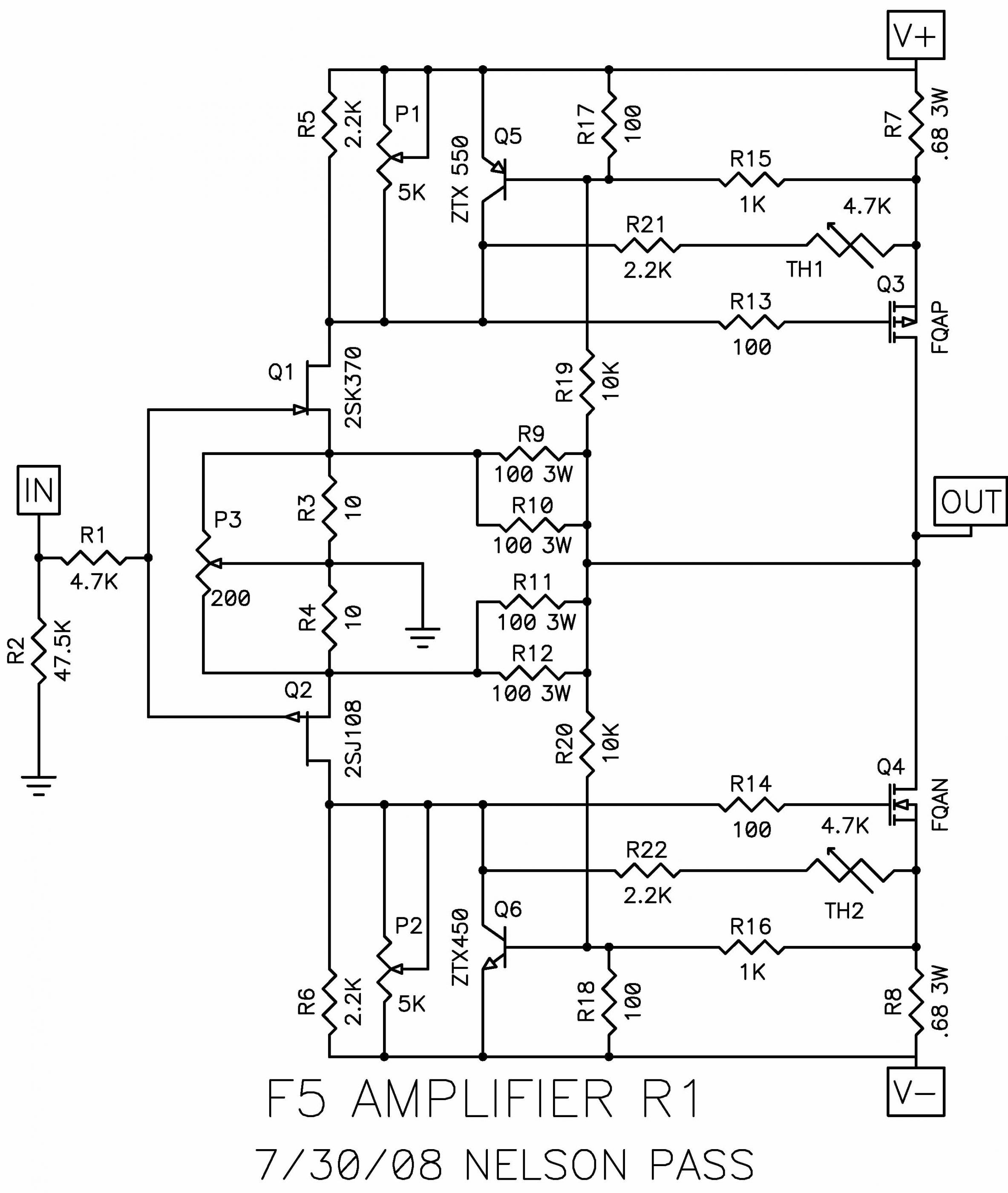
10856 has the SCH with P3
That is the new flawor and big bomb drop (in a good sense) Papa give us.
http://www.diyaudio.com/forums/atta...1d1313021202-f5-power-amplifier-f5-r1-sch.jpg
AS PCB goes not made so far?
10856 has the SCH with P3
That is the new flawor and big bomb drop (in a good sense) Papa give us.
http://www.diyaudio.com/forums/atta...1d1313021202-f5-power-amplifier-f5-r1-sch.jpg
AS PCB goes not made so far?
Last edited:
Did it sound better?
I added P3 to my F5’s and could dial in the null very easily. I didn’t like it that way though, so I made second harmonic dominant by 10 dB, its sounded better this way to me though I may go higher. The big change for me was the ability to get the phase of the second harmonic in phase with the test tone. The imaging seams more stable after the modification. It is fun to have a new tool, I find myself testing all my amps to look at the spectrum. Just a note: The BA-3 has much higher distortion and sounds great, so there is more to it than just the numbers.
- Home
- Amplifiers
- Pass Labs
- F5 power amplifier