this "new circuit" has nothing to do with F5...what about this circuit? It is circuit based on the schematics from earlier post (moskido schematics), but it should have no temperature drift already. Do you know how to adjust bias on this scheme? If I wanted to implement temperature thermistor, where should I connect it?..
Please start a new thread if you want to post schematic and discuss details.
I wanted to comment in this, the longest thread ever. My dual pair output F5 has been providing me great music (and keeping my room warm) since mid-2009, the last adjustment required was a bias tweak 12/2009 when I verified that after months of use temperature and bias was in check. I checked again today, exactly the same as I set it back in '09. Still sounds great.
Thanks for the music!
Thanks for the music!
Many pages back there was a long discussion of mounting transistors to heatsinks. I do not have a deep background in thermodynamics or electronics, but have been building amps for many years as a hobby, mostly when big metal TO-3 cases with two bolts were the norm, and rarely with FETs. But only recently have I become interested in class-A since my tube days. One major contraint seems to be that the FET (or other transistor) mounting surfaces need to be electrically insulated from each other but thermally conductive to the heatsink, and the FETs thermally conductive to each other. The trend toward smaller and poorly secured thermally-conductive area thru the electrical insulator seems to be a constraining or at least less than ideal factor, especially with mfgrs' focus on cost and miniaturization making the tabs and mounts smaller, thinner, and less effective or reliable, (or at least sometimes less than ideal).
Consider instead mounting the device directly (NOT electrically insulated) to some kind of mounting pad or block that expands the heat-conducting electrically-insulating area signifcantly and electrically insulating that "pad/block" from the heat sink instead.
I am considering mounting each FET to (for one example) its own 6" long 1" X 1" cross-section block of copper without electrical insulation (each pad/block remains electrically "hot" to the device mount); then mount each copper block (with its length vertical) alongside each other horizontally with a small space between, with each block electrically insulated (via a large area of sheet mica or some such electrical insulator and thermally conductive heat-sink compound and insulated screws), to a very large aluminum heat sink (with a very thick solid base before the finning starts). This would provide far better thermal coupling from the devices to the heatsinks, and ultimately also to each other as the entire structure is much better thermally coupled thru the far greater coupling area.
My questions:
1) Will my proposed very large area of electrical insulation cause problematic capacitance? Does the mica or other (silicone? plastic?) insulator have significant dielectric constant? If too much insulation area becomes problematic, is there an acceptable max or ideal electrically-insulating/heat-conducting area?
2) Are usable larger or sheet insulators available? Since the device mounts to the block, the block can be permamently mounted to the heat-sink; so couldn't a thin layer of epoxy paint be cured as insulator, then the blocks epoxied to the heat-sink?
3) Someone hundreds of pages back mentioned HF oscillation unless the heatsink was grounded. Will the large blocks (inside the enclosure) cause problems by being electrically "hot"? Are there implications for choosing the FET case type, as TO-3 cases will conduct thru these blocks, whereas I assume "TAB" type mounts will conduct thru their pins? What are the possible problems I should be aware of due to these electrically hot blocks mounted next to each other, for choosing their shape etc.? What about capacitance with the air as dielectric? Or tuned-length RF antenna effects?
4) This complete assembly wil have significant mass (which doesn't bother me) and thermal mass. Will it be a problem that it takes a longer time to reach average running temperature and stabilize?
5) There are many minor design variations possible, with the blocks electrically insulated and heat-conductive on more than just one side, or different-shaped or tapering blocks etc. Any optimising ideas?
6) I have high-quality thermally-conductive potting epoxies with various heat-conductive fillers and various electrical insulating and dielectric qualities. I have considered gluing the copper bars permanently, with only extremely thin spacers or epoxy paint layers to provide positive electrical insulation. Is any dielectric nature of the epoxy and filler likely to be a big concern? Could this be thinner and conduct heat better than mica, yet insulate electrically?
7) OK I'm really showing my ignorance on these tab devices: is the tab electrically usually connected to a high-impedance input, lower-impedance output, or stiff supply connection? How concerend do I need to be about the resistance and capacitance across the larger insulator area?
8) On tab-type transistor cases, though the metal tab is designed to conduct most of the heat, sometimes the device top is still noticeably warmer than what it's bolted to. I would expect some small amount of additional cooling to result from a secondary heatsink atop the device, on the side not mornally mounted to; perhaps a finned bar across the tops of the FETs with a couple of large -diameter aluminum bolts between the devices to the main heatsinks. Seems like it could help; assuming insuficient presure to crush, could it hurt anything?
9) I'm a relaitive newbie on-list, mostly searching and reading, so if this all is covered elsewhere, please help direct me. And I apologize if this is a little OT on the thread.
Last edited:
The extra copper spreader is used, but rarely.
Yes, large sheets of thermally conductive, electrical insulators are made and available.
if your top to bottom dimension is 6" then the longest radius from device to top corner is likely to be <4". Using aluminium, the thickness of this spreader can be reduced to 1/10 of that maximum radius. For a copper spreader, one could work with slightly thinner, maybe 1/12 or even 1/15 of radius.
That gives the spreader thickness of 0.4" to 0.3", You can save money and space and weight by adopting thinner than 1".
Andrew, thanks. Indeed I didn't make any attempt to optimize the thickness so I was way off.
Bergquist Sil-Pad? Looks like good stuff.
Even scaled down it sure seems there's a big benefit to be had from mounting the device without an insulator to the pad, and having a larger insulator between pad and sink. I'm surprised nobody makes some such commercial "heat sprreader". I guess this all assumes problems with standard mounting.
@cyclecamper:
Using a heat spreader has advantages, but in other ways.
As long as the heat transfer resistance of the thermal pad is constant (does not depend on power density), the size of the area where heat is conducted does not matter. Meaning wether it's the small area of a TO-247 package or the large area of the heat spreader, always the same heat flow has to be transfered to the actual heatsink. So, in both cases the fet runs at the same temperature.
However, if one uses a heat spreader made of a material that conducts heat better than the heatsink material (usually aluminum), like e.g. copper, the heat is more effectively carried away from the fet in the first place.
Any case, happy experimenting")
Hannes
Using a heat spreader has advantages, but in other ways.
As long as the heat transfer resistance of the thermal pad is constant (does not depend on power density), the size of the area where heat is conducted does not matter. Meaning wether it's the small area of a TO-247 package or the large area of the heat spreader, always the same heat flow has to be transfered to the actual heatsink. So, in both cases the fet runs at the same temperature.
However, if one uses a heat spreader made of a material that conducts heat better than the heatsink material (usually aluminum), like e.g. copper, the heat is more effectively carried away from the fet in the first place.
Any case, happy experimenting
Hannes
As long as the heat transfer resistance of the thermal pad is constant (does not depend on power density), the size of the area where heat is conducted does not matter. Meaning wether it's the small area of a TO-247 package or the large area of the heat spreader, always the same heat flow has to be transfered to the actual heatsink. So, in both cases the fet runs at the same temperature.
Not true if the heat conduction of the electrical insulator is relatively poor. Moving the insulator from the small area and large heat differential of the device footprint to the large area and small heat differential of the spreader is my objective.
But thank you for your new point; copper or silver near the device may outperform the aluminum of the sink in that immediate area. I hadn't really thought in depth about that; about the conduction within the material itself. That kind of thinking is probably fundamental to anyone with formal training in it, or who has seen color 3-D graphs of the temps.
Last edited:
Not true if the heat conduction of the electrical insulator is relatively poor.
with classA, I hope its not
are you forgetting that with added heat spreader you have yet another material, and yet another connection
that itself would result in loss of heat transfer
this have been debated for year now
I'm surpriced noone haven't shown any data to prove efficiency of heatspreader
shoudn't be too hard
Not true if the heat conduction of the electrical insulator is relatively poor.
See it as electrical circuit - if you use a single small resistor or many large ones in parallel does not matter.
Think in terms of flow, if you impede small flow with a large area with little resistance it's the same as impeding it a strong flow with a small area and high resistance. Because in the end, what matters is only the amount of power (power density times area) and heat resistance (constant value). Changing the power density by changing the area does not affect the product of the two.
Anycase, discussion is academic, copper always looks better
Hannes
Last edited:
That is exactly what the manufacturer does inside the power package to improve heat transfer and reduce thermal impedance.are you forgetting that with added heat spreader you have yet another material, and yet another connection
this conclusion is complete rubbish.that itself would result in loss of heat transfer
Copper Spreader
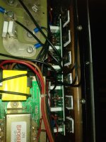
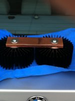
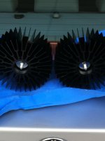
This is what I'm doing with my F5 copper to aluminum heat sinks. I have decided to isolate the output transistors so I am using 2 of these on each of my monoblocks. I am using diamond paste to attach the sinks to the copper bar. I will also be using diamond paste at the transistor on the copper bar as well. The heat sinks are mounted in compression using valve springs at around 180 psi on the inside of the heatsink. This should cancel out any thermal expansion differences between the copper and the aluminum. I also don't know too much about about thermal dynamics so I went for the brute force approach; not to mention getting a price break on the qty of heatsinks I purchased...
This is what I'm doing with my F5 copper to aluminum heat sinks. I have decided to isolate the output transistors so I am using 2 of these on each of my monoblocks. I am using diamond paste to attach the sinks to the copper bar. I will also be using diamond paste at the transistor on the copper bar as well. The heat sinks are mounted in compression using valve springs at around 180 psi on the inside of the heatsink. This should cancel out any thermal expansion differences between the copper and the aluminum. I also don't know too much about about thermal dynamics so I went for the brute force approach; not to mention getting a price break on the qty of heatsinks I purchased...
Attachments
optimum preamp for Pass F5
Hi, I hope I am posting in the right place.
I'm getting ready to start a diy build from nothing. So, I have no limits whatsoever in selection of my project (speakers, too). I have been lurking for quite a while, and it looks like the Pass amplifiers are very well supported and liked on this forum. So, I think I am going to build one.
My dilemma is matching the preamp to the amp. I see in a number of threads that the pass F4 is commonly matched with the Impasse tube amp and the Pass Pumpkin preamp.
I am also considering building an F5, I think I would actually prefer to build the F5. However, I don't see any consensus on which preamp is optimum for it. Maybe it is not a big deal...just use any old preamp? B1? Impasse? Pumpkin? Heretical?
Thanks in advance for any advice.
Andy
Could you define what your terms are/mean?
Sure;
power density=heat flow/area=amount of heat energy** per second per m^2
heat resistance=1/thermal (heat) conductivity -> heat transfer equivalent term of a resistor, defines the temperature difference created when a unit heat flow is conducted (unit: degree Celsius per Watt). From the unit one can see that this property does not depend on the area or power density, only on the heat power transfered. It does not bother wether its a large area with low power density or a small area with a large one.
Hope this helps! Hannes
**heat energy=power dissipation of the fet in this case
Quite some people like to match it with the Pass B1, or its improved DC-coupled version DCB1.Hi, I hope I am posting in the right place.
I'm getting ready to start a diy build from nothing. So, I have no limits whatsoever in selection of my project (speakers, too). I have been lurking for quite a while, and it looks like the Pass amplifiers are very well supported and liked on this forum. So, I think I am going to build one.
My dilemma is matching the preamp to the amp. I see in a number of threads that the pass F4 is commonly matched with the Impasse tube amp and the Pass Pumpkin preamp.
I am also considering building an F5, I think I would actually prefer to build the F5. However, I don't see any consensus on which preamp is optimum for it. Maybe it is not a big deal...just use any old preamp? B1? Impasse? Pumpkin? Heretical?
Thanks in advance for any advice.
Andy
There may be no such a thing as a best preamp for it, some people like a tube flavour, others like whatever-is-it while not having OPAMPs...
Hi, I hope I am posting in the right place.
I'm getting ready to start a diy build from nothing. So, I have no limits whatsoever in selection of my project (speakers, too). I have been lurking for quite a while, and it looks like the Pass amplifiers are very well supported and liked on this forum. So, I think I am going to build one.
My dilemma is matching the preamp to the amp. I see in a number of threads that the pass F4 is commonly matched with the Impasse tube amp and the Pass Pumpkin preamp.
I am also considering building an F5, I think I would actually prefer to build the F5. However, I don't see any consensus on which preamp is optimum for it. Maybe it is not a big deal...just use any old preamp? B1? Impasse? Pumpkin? Heretical?
I can certainly recommend Salas excellent DCB1; even better when used in conjunction with an LDR type attenuator.
http://www.diyaudio.com/forums/analog-line-level/171715-salas-hotrodded-blue-dcb1-build.html
http://www.diyaudio.com/forums/analog-line-level/80194-lightspeed-attenuator-new-passive-preamp.html
Thanks in advance for any advice.
Andy
- Home
- Amplifiers
- Pass Labs
- F5 power amplifier