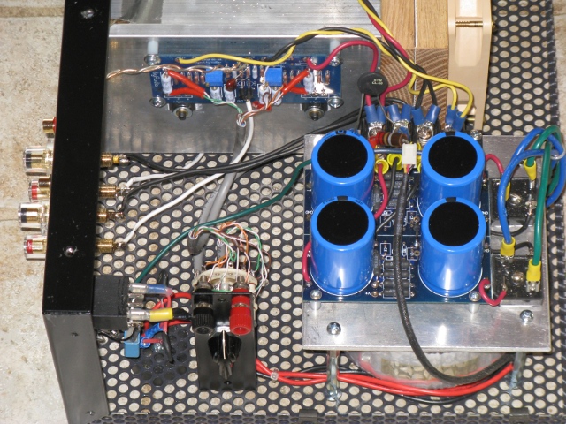
looks like a good candidate for those who need to use 'double heatsinks'
Anilva, neat and tidy
and I like the 'upside down' mounted boards, placing outputs at lower half of heatsink
Thanks. If you notice the board is mounted normally and not upside down. Makes sense to have the MOSFETs positioned lower on the heatsink.
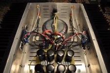
That's my question. Given the fact that the toroid is adequate for the current draw, why should it have mechanical hum - unless the Toroid is under-powered (which I suspect is not) or there is a problem with the winding.500VA should be sufficient for 4 MOSFETs (in total) at 32W each.
Patrick
If it IS a problem, add a mains dc trap after the fuse - plenty designs this site - simple and work well.
I tried measuring if there is any sort of DC on the mains line, I couldn't measure any. Do I put a DC trap?
Hi everyone... I am building an F5. I have everything done and a couple of nights ago I fired it up for the first time.
First channel... Great! Got the DC offset down to 1mV and it is pretty stable.
Second channel it was going well until.... SMOKE!!! I am not sure what happened. I only have one Multimeter so I had to keep going back and forth and I believe that I might have set the bias too high.... but I am not sure.
Now I need to find what I burned... I turned the variac down really fast so there is no evident sign of where the smoke was comming from. Any Ideas?
Is there an easy way to test the low noise Jfets to see if they are blown? Should I look somewhere else?
Thabnks
First channel... Great! Got the DC offset down to 1mV and it is pretty stable.
Second channel it was going well until....
SMOKE!!! I am not sure what happened. I only have one Multimeter so I had to keep going back and forth and I believe that I might have set the bias too high.... but I am not sure.Now I need to find what I burned... I turned the variac down really fast so there is no evident sign of where the smoke was comming from. Any Ideas?
Is there an easy way to test the low noise Jfets to see if they are blown? Should I look somewhere else?
Thabnks
CeeVee's F5
Hi all,
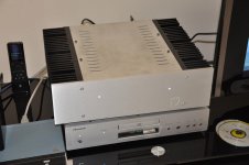
Here are some pictures of my rendition of Papa's fantastic F5
I kept it as stock as possible for me so i would have a reference for things to come.
The initial sound is all i expected: fantastic...it's all been said in these pages.
pictures are of:
Initial low bias warm up....no Dc to speak of on output
Inside layout
First song with my Shanling drek as source ( new IV stage and russian coupling caps )
Hi all,
Here are some pictures of my rendition of Papa's fantastic F5
I kept it as stock as possible for me so i would have a reference for things to come.
The initial sound is all i expected: fantastic...it's all been said in these pages.
pictures are of:
Initial low bias warm up....no Dc to speak of on output
Inside layout
First song with my Shanling drek as source ( new IV stage and russian coupling caps )
Attachments

Hi everyone... I am building an F5. I have everything done and a couple of nights ago I fired it up for the first time.
First channel... Great! Got the DC offset down to 1mV and it is pretty stable.
Second channel it was going well until....
Now I need to find what I burned... I turned the variac down really fast so there is no evident sign of where the smoke was comming from. Any Ideas?
Is there an easy way to test the low noise Jfets to see if they are blown? Should I look somewhere else?
Thabnks
I had exactly the same experience with my first F5 build. The first channel came up just fine. While adjusting the 2nd channel and going back and forth making bias adjustments, all of a sudden I got smoke and both Mosfet source resistors started to glow. Apparently I shorted something with one of my multimeter clips. I solved the problem for by installing a rotory switch and some wiring for the bias adjustments.
Hi Cee Vee,Hi all,
Here are some pictures of my rendition of Papa's fantastic F5
I kept it as stock as possible for me so i would have a reference for things to come.
The initial sound is all i expected: fantastic...it's all been said in these pages.
Congratulations!
your amp looks Fantastic!

I'm building a stock F5 too, is not finished but sounds great!
I have a thread about F5 in a Portuguese forum.
Regards
Carlos

may I say Fugly! ?

Thanks ZM, may i say that after a lengthy burning in period the Shanling you helped me mod is now amazing with the new Russian caps for coupling.Puts my Arcam CD73 to shame....and the Shigaclone is not as good either ( yet !).
It's easily the reference ...really fantastic through my UGS to show off the sound of F5...although it's early days the sound is already gorgeous.
But then again since there are no caps in signal path i don't expect much character change in the sound, just a bias fine adjust a few weeks down the road.
Last edited:
Any views/feedback on Remote/IR Volume control?
Hi,
I am planning to use similar ebay item as a input selector/volume control in front of F5.
Is this a good idea. Any feedback or views on this item and would it be good enough to be front-ending a F5?
I need to be able to adjust volume and select 2-3 input sources to play my F5 and I found this on ebay.
Remote Input Selector & Volume Control DIY KIT MV02 | eBay
Cheers.
MV-02 remote kit
I just got mine working.
It is VERY slow.
At start up, the selected LED indicates which channel will come on and flashes for about 13 to 14 seconds. Just before this time delay expires (after ~12seconds) the selector relay pulls in and signal is passed from input to output.
When changing channel, the previous channel switches off almost instantly leaving the output connected back through the pot to the open circuited input with all relays open. The newly selected channel LED flashes for that same 13/14 seconds delay and about 12 seconds into that delay the new relay pulls in.
I did not wire up the monitor function. I used one of those as a 5th input.
The mute function mutes for that 13 to 14seconds and then the existing channel passes through to output. It is a temporary mute only.
Can the Atmel at89c51 be reprogrammed?
The motorised pot is not of good quality. I would never use it with an amp of the caliber of any Pass design. I have mine driving a couple of chipamps.
I do plan to use the second kit motor pot to control an LED/LDR volume control The LDRs are in the audio channel. The pot is only adjusting current to the LEDs. It has a common ground pin to both tracks. I have not dismantled the pot yet. This means it cannot be used (in it's standard form) to send opposite signals to the LEDs like a Lightspeed does.
Since connecting up the Control board I have a very high noise from the amp. 3.9mVac & 14mVac on the channels whereas they measured 0.0mVac to 0.5mVac depending on which connections were made on the input.
I will need to investigate if it's down to the digital processing. It runs from a separate tiny EI transformer.
Last edited:
I just got mine working.
It is VERY slow.
At start up, the selected LED indicates which channel will come on and flashes for about 13 to 14 seconds. Just before this time delay expires (after ~12seconds) the selector relay pulls in and signal is passed from input to output.
When changing channel, the previous channel switches off almost instantly leaving the output connected back through the pot to the open circuited input with all relays open. The newly selected channel LED flashes for that same 13/14 seconds delay and about 12 seconds into that delay the new relay pulls in.
I did not wire up the monitor function. I used one of those as a 5th input.
The mute function mutes for that 13 to 14seconds and then the existing channel passes through to output. It is a temporary mute only.
Can the Atmel at89c51 be reprogrammed?
The motorised pot is not of good quality. I would never use it with an amp of the caliber of any Pass design. I have mine driving a couple of chipamps.
I do plan to use the second kit motor pot to control an LED/LDR volume control The LDRs are in the audio channel. The pot is only adjusting current to the LEDs. It has a common ground pin to both tracks. I have not dismantled the pot yet. This means it cannot be used (in it's standard form) to send opposite signals to the LEDs like a Lightspeed does.
Since connecting up the Control board I have a very high noise from the amp. 3.9mVac & 14mVac on the channels whereas they measured 0.0mVac to 0.5mVac depending on which connections were made on the input.
I will need to investigate if it's down to the digital processing. It runs from a separate tiny EI transformer.
Thanks Andrew. I was quite skeptical of the unit and hence posted my question. I have recently completed a BOZ-J and sounds very nice. Wanted to add volume and input selector. May need to resort to traditional methods now.
Cheers.
Can the Atmel at89c51 be reprogrammed?
Theoretically yes, though you need somebody with a prototyping board and the source code of the kit (and with some spare time).
Hannes
LDR designs use to have a lowish impedance pot, like 1K or 10K. How are you planning to arrange it to be able to use the provided 100k pot?I do plan to use the second kit motor pot to control an LED/LDR volume control The LDRs are in the audio channel. The pot is only adjusting current to the LEDs. It has a common ground pin to both tracks. I have not dismantled the pot yet. This means it cannot be used (in it's standard form) to send opposite signals to the LEDs like a Lightspeed does.
You're right, sorry, my fault. I was thinking in the Lighter note, which uses 1k dual pot.Hi Regi,
Lightspeed uses a dual track log 100k wired in opposite directions as the current control for the LEDs.
The LDRs do not need a pot, nor resistor.
It's the common ground that causes the problem for "wired in opposite" directions.
Low powered F5
I had to make use of a spare chassis and few old 22-0-22 transformers lying around with me. So I built my 3rd F5 with these parts.
Firstly the transformers are not toroids, but CRGO E&I type. They are mid-sized and not high powered - must be around 100-150VA (don't remember from those days). Therefore I made two independent power supplies to feed one channel each. These are two monoblocks except the power cord and the switch.
Without connecting the amp boards, the power supplies measured +/-28VDC.
Biased up well straight away. No problem. Could run upto 500mV through R11 and R12. The power supply measures +/-21V. The amp is stock circuit. Sound terrific as always with Papas designs. No hum, no noise - nothing, but pure music.
Ran the amp for about 4 hours. No problem. The transformers were getting little warm and that's about it. Heatsinks are warm and as expected, not hot, since the MOSFETs are not biased high.
I am sure the amp is now a 15-16W amp, but sounds great. How far can I push the bias to know the limits of the transformer? Observe the fall in rail voltages or how hot the transformers are running at? Any insights on operating the MOSFETs at lower bias levels in a F5? To my mind this has become a sort of Mini-F5.
Cheers.
- Home
- Amplifiers
- Pass Labs
- F5 power amplifier