I have three 1240VA transformers that I picked up on ebay a while ago. Problem is... 29V output at no load and 27.2 at 19Amps. What do you guys think about using a voltage regulator to drop the voltage down to 24V (voltage would differ I guess depending on placement of the regulator)? If you think its not a problem would you put the regulator circuit between the transformer and the power supply or between the power supply and the amp?
Thanks
Uriah
figure I might add some info on these
Primary is 120V 50Hz
Secondaries are 27.2V at 19Amps
Secondaries are 29.6V at No Load
Primary resistance 2x(.34+.13)
Secondary resistance 4x.065 ohm
Temp rise at 1240VA is 80 deg C
P/N is TI-043222B AU Iss 0 from Toroid International Ltd.
DIA is 165mm and Height s 98mm weight is 10.2kg
udailey said:I have three .......
seems that using cap multipliers ( with mosfets as pass elements) is logical ....
udailey said:What do you guys think about using a voltage regulator to drop the voltage down to 24V (voltage would differ I guess depending on placement of the regulator)? If you think its not a problem would you put the regulator circuit between the transformer and the power supply or between the power supply and the amp?
I would use ZV5 regulator, but with C-R-C filter instead of C-L-C.
The total heat dissipation/channel is the same whether you have
the regulator or not.
udailey said:29V output at no load and 27.2 at 19Amps.
Mmm, (cough), let's hope these are DC numbers.
I read about voltage dividers on this site after reading Zen Mod's response:
http://www.aikenamps.com/VoltageDividerRule.htm
I came up with this:
Capacitive dividers can be used with AC input signals.
Vout = Vin*C1/(C1+C2)
Example: In the following circuit, the output voltage could be: Vout = 28VAC*1uF/(1uF + 0.22uF) = 22.95VAC. Note that the output voltage is not dependent on the input frequency. However, if the reactance of the capacitors is not large at the frequency of interest (i.e. capacitance not large enough), the output current capability will be very low.
I tried to stick a pic in here. Dont know where it went, but here is the link.
http://picasaweb.google.com/udailey/Projects/photo#5208075545305807906
So can I just use this on the secondaries before the rest of the power supply circuit?
If I can, then does this little circuit go on the + and - of the secondary or just on one of them?
Thanks so much,
Uriah
http://www.aikenamps.com/VoltageDividerRule.htm
I came up with this:
Capacitive dividers can be used with AC input signals.
Vout = Vin*C1/(C1+C2)
Example: In the following circuit, the output voltage could be: Vout = 28VAC*1uF/(1uF + 0.22uF) = 22.95VAC. Note that the output voltage is not dependent on the input frequency. However, if the reactance of the capacitors is not large at the frequency of interest (i.e. capacitance not large enough), the output current capability will be very low.
An externally hosted image should be here but it was not working when we last tested it.
I tried to stick a pic in here. Dont know where it went, but here is the link.
http://picasaweb.google.com/udailey/Projects/photo#5208075545305807906
So can I just use this on the secondaries before the rest of the power supply circuit?
If I can, then does this little circuit go on the + and - of the secondary or just on one of them?
Thanks so much,
Uriah
udailey said:I read about voltage dividers on this site after reading Zen Mod's response:......
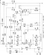
what I meant is really like this cap multiplier implemented in F3 (look attachment) .
that way you'll loose 4-5V with benefits .....
Attachments
Hmm. Really does not make any sense to me. I wont try to pretend that I get it ") But I will try to understand it so I dont waste anyones time.
But I will try to understand it so I dont waste anyones time.
I tried reading up on voltage multipliers but for my situation it really didnt make sense. Plus that F3 is the amp not the power supply where I have the problem, but then again I dont understand the circuits anyway and I kind of need to be led by the hand at this point.
If I have a schematic I can replicate it and maybe even have it work but I dont actually understand the circuit. I do understand algebraic equations in circuits. So if you were to say I need to use a voltage divider circuit with Vout=Vin*C1/(C1+C2) and put that circuit on each secondary lead in between the transformer and the rest of the PSU circuit, then I would understand how to do that. But right now thats the limit of "getting it" for me.
In short, I am still left baffled. It seems like you guys think its possible for me to use my 27-29Vout transformer and it would probably save me a lot of money to be able to do that. Is there a simple way to do so? If you would be so kind as to show me I certainly would appreciate it.
But I will try to understand it so I dont waste anyones time. I tried reading up on voltage multipliers but for my situation it really didnt make sense. Plus that F3 is the amp not the power supply where I have the problem, but then again I dont understand the circuits anyway and I kind of need to be led by the hand at this point.
If I have a schematic I can replicate it and maybe even have it work
but I dont actually understand the circuit. I do understand algebraic equations in circuits. So if you were to say I need to use a voltage divider circuit with Vout=Vin*C1/(C1+C2) and put that circuit on each secondary lead in between the transformer and the rest of the PSU circuit, then I would understand how to do that. But right now thats the limit of "getting it" for me. In short, I am still left baffled. It seems like you guys think its possible for me to use my 27-29Vout transformer and it would probably save me a lot of money to be able to do that. Is there a simple way to do so? If you would be so kind as to show me I certainly would appreciate it.
OK, problems solved -- I put a 1,000uF/35V cap on each of the rails immediately adjacent to the trimpots -- any lead length here adds to the stray capacitance. I haven't sought to optimize the value -- I bought jizillions of the capacitors from Tektronix 7 or 8 years ago.
Secondly -- I put 3.3n/100V polyester across R5 and R8. The ringing on the square wave test (200kHz, 1 Watt) is almost gone. Good enough for me. I tried values from 470pF to 47nF and these work best for me. YMMV.
THD% for 1W, 1kHz is now 0.0063% from 400Hz to 80kHz without any trimming of the source resistors on the JFETs or MOSFETs, and without any attempt to get rid of extraneous noise -- so without too much difficulty it can probably be brought down much lower still, i.e. to the levels seen in the article. I am using Fairchild devices, no thermal protection, etc., etc.
The THD% is still mostly 2nd order, however.
Funny thing about the Fairchild devices -- the Vgs for a batch of them are pretty tight, but the P's and N's are over 1.4V apart.
udailey said:Hmm. .....
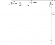
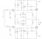
is this make a sense ?
cap multiplier is same as series voltage reg ( where output voltage is set with zenner voltage , minus Uds of series mosfet) ;
there is just one tiny difference - lack of zenner
so - voltage on output will be always input voltage less Uds .
say that our start was series zenner reg ;
we took zenner from it , but we further augmented value of cap which was placed across zenner terminals ; there is point in name "cap multiplier" ...... just becasue mosfet have his own characteristic , known as "multiplication factor " , it will multiply value of that cap ......
some ppl like to say that cap multiplier isn't much different from plain choke ;
simplified it is , but in your case - exactly convenient , because Uds is always in ballpark of 4V , and that's exact amount of voltage you want to shave from your PSU .
further simplified - if you put adequate mosfet in line with each (and both) (positive and negative ) legs of PSU , you'll loose approx. 4V of voltage , in each leg.
Attachments
udailey said:Hmm. Really does not make any sense to me. I wont try to pretend that I get it
I tried reading up on voltage multipliers but for my situation it really didnt make sense. Plus that F3 is the amp not the power supply where I have the problem, but then again I dont understand the circuits anyway and I kind of need to be led by the hand at this point.
If I have a schematic I can replicate it and maybe even have it work
In short, I am still left baffled. It seems like you guys think its possible for me to use my 27-29Vout transformer and it would probably save me a lot of money to be able to do that. Is there a simple way to do so? If you would be so kind as to show me I certainly would appreciate it.
I would guess that those in the know would suggest that you look for a different transformer. As it sits, you'd have nearly 40 VDC after rectifying and filtering.
Cheers,
7/10
distortion
Jack, have you had a chance to see if you can 'hear' a difference here?
I dont have a scope, can probably borrow one from work....
I am wondering if this amp will be hard to keep sounding as expected without some serious DIY tools.
I look forward to understanding these tweaks that maybe needed as DIY F5's come to fruition.
Mike
jackinnj said:
THD% for 1W, 1kHz is now 0.0063% from 400Hz to 80kHz without any trimming of the source resistors on the JFETs or MOSFETs, and without any attempt to get rid of extraneous noise -- so without too much difficulty it can probably be brought down much lower still, i.e. to the levels seen in the article. I am using Fairchild devices, no thermal protection, etc., etc.
The THD% is still mostly 2nd order, however.
Funny thing about the Fairchild devices -- the Vgs for a batch of them are pretty tight, but the P's and N's are over 1.4V apart.
Jack, have you had a chance to see if you can 'hear' a difference here?
I dont have a scope, can probably borrow one from work....
I am wondering if this amp will be hard to keep sounding as expected without some serious DIY tools.
I look forward to understanding these tweaks that maybe needed as DIY F5's come to fruition.
Mike
jackinnj said:I put a 1,000uF/35V cap on each of the rails immediately adjacent to the trimpots -- any lead length here adds to the stray capacitance.
Secondly -- I put 3.3n/100V polyester across R5 and R8. The ringing on the square wave test (200kHz, 1 Watt) is almost gone. Good enough for me. I tried values from 470pF to 47nF and these work best for me. YMMV.
THD% for 1W, 1kHz is now 0.0063% from 400Hz to 80kHz without any trimming of the source resistors on the JFETs or MOSFETs, and without any attempt to get rid of extraneous noise -- so without too much difficulty it can probably be brought down much lower still, i.e. to the levels seen in the article. I am using Fairchild devices, no thermal protection, etc., etc.
The THD% is still mostly 2nd order, however.
Funny thing about the Fairchild devices -- the Vgs for a batch of them are pretty tight, but the P's and N's are over 1.4V apart.
That's great. I haven't tried extra decoupling, but I'll play with it
next chance.
If you can still see 2nd harmonic at 1W, then some Source power
resistor trim can probably take that lower yet. If you see the
2nd harmonic positive lined up with the positve output, then
you want to slightly reduce the resistor on the N channel device,
and vice versa. Wit this I routinely get .001% to .002%.
I don't really hear a difference on that, but I don't see any
reason not to nail it if you have an analyzer.
And yes, my P's are over a volt higher Vgs also.
Re: distortion
I think that this will work great just out of the box, not requiring exotic tools at all. Just be mindful of keeping the leads as short as possible on the input stage.
mithomas said:Jack, have you had a chance to see if you can 'hear' a difference here?
I dont have a scope, can probably borrow one from work....
I am wondering if this amp will be hard to keep sounding as expected without some serious DIY tools.
I look forward to understanding these tweaks that maybe needed as DIY F5's come to fruition.
Mike
I think that this will work great just out of the box, not requiring exotic tools at all. Just be mindful of keeping the leads as short as possible on the input stage.
For the moment I was replicating NP's setup -- thus I had ONE 1K resistor to both gates of the JFET's and 100K from gate to ground.
I am just using Dale 5W 50R resistors as I have a few hundred in stock. Thus 2 100R in parallel are unnecessary.
I have 1000u/35V at each rail. The potentiometer (trimpot) is part of the input so it really likes the power supply end at a very low impedance source. Elsewise it is having its immoral phase relationship with the C(gate-drain) of the JFET.
mithomas said:
If your talking about the owners manual then yes. I think there is a problem.
My personal feeling is that Nelson is still trying to get us to figure out the PS differences from the unregulated F4, if any, or how to sneak a few more volts in. The sixmoons article looked to be the same.
the users manual, which also contains the F5 article, works for me now:
http://www.firstwatt.com/downloads/F5-om_sm-080527.pdf
lots of tasty things in there, especially the last page
-Jared
- Home
- Amplifiers
- Pass Labs
- F5 power amplifier