Nelson Pass said:
Hey! That looks like my amp!
")
Weird huh?
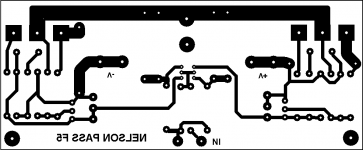
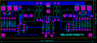
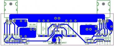
Juma, very nice board design . Visually it expresses the simplicity of the circuit well, and as you mentioned, it seems to have all the requirements of those of us commenting, and that's hard to do
Maybe someone will do a board run, but it is even better that lots of people seem to be making their own boards!
Mark
Maybe someone will do a board run, but it is even better that lots of people seem to be making their own boards!
Mark
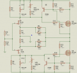
massimo said:Did anybody noticed that in the close up picture in post #926 at the top of this page Nelson added a 2.4 ohms resistor in parallel to the 0.47 ohm source resistor of the Nch mosfet (Q4)?
Moreover, the gate resistor seems to be 150 ohms in lieu of 47 ohms indicated in the published schematics. (Assuming that the left hand resistor close to the gate is R14)
A special tweaking or........???
Who know the answer,please ?
thomasfw said:
Who know the answer,please ?
2.4R in parallel probertly gives te best balance in current and you might mix the gate resistor with the 150R used for current limiting...
Variac said:... it is even better that lots of people seem to be making their own boards!
Mark
Of course !
"Do It Yourself !" said the burning bush (it was on the second tablet - the one that Mel Brooks dropped)
Skorpio said:2.4R in parallel probertly gives te best balance in current and you might mix the gate resistor with the 150R used for current limiting...
The 2.4 ohm resistor was used to trim for lowest distortion, which I
do if the channel exceeds .005% at 1 watt. As I have said, you need
an analyzer to be able to do this. A minority of channels need this,
and it is random in value and placement.
Nelson Pass said:
Hey! That looks like my amp!
If the Zen Master says so I supposedly that I drawed the circuit right
thomasfw said:Will ZTX450 more stable in compare with using MPSA18 ?
They would be sleeping, probably over the life of F5 operation...
Forget their stability, grab any one and use it...
- Home
- Amplifiers
- Pass Labs
- F5 power amplifier