Sorry Tinitus, that I didn't make much sense - happens too often here, unfortunately!
Let's look at things a bit differently ...
It's not so much the 0.5W it'll dissapate but what happens to the sound when you pass 5mA thru that pot's wiper's very light contact point, particularly if you like to use those little cermet multiturn trimpots - it's the weak point of any variable pot (the multiturn ones are particularly light duty), hence the benefits of the multi-step switched resistor vol control, etc
The easy way to find out is just pull one pot out, measure it and replace it with a same value resistor and compare the sound difference - it's quite remarkable. The next best thing you can do is reduce the work that it does (current) and hence the influence it has on the sound generated by the 7mA thru the front end of the amp (the jfets).
The reference is the Figure 6 in the "F5 Power Amplifier" article at "First Watt" website.
I've tried all sorts of pots, including those vol control stepper ones with the mox SMDs, etc, and found the same conclusion as many before me, "no pot" is the "best pot" in the signal path if possible.
There may well be really good pots that will do the job perfectly, but I can't find any, apart from the Texas Component (Vishay) ones and then will need some matching quality Z foil resistors - not rushing into that as not cheap components at all - will try making some of the Manganin Resistance wire ones before that, I think.
Regi,
That link about using those quiet cooling system of the CPUs is rather interesting - is the temp controlled by on/off system or variable fan speed? ie, a 130W cooler would run rather slow for a 62W F5 heat input and be nearly totally silent, yes?
The much closer grouping of the o/p Fets to the cooling plate would make thermal tracking so much tighter, smaller pcbs like Peter Daniels ones, quicker heatup times, no big heatsinks or cases, ....
Hmmmmm! Interesting, indeed.
Excellent! I had no idea the circuit would drive that many outputs as is. Bias or other supply differences I suppose? Higher voltage rails? Larger heat sinks?
I'm getting ready to buy some more heatsinks, more F-5 amps need built, this sounds very interesting.
Russellc
I am running at 2 Amps (around 100W of heat per channel) I am using 1 conrad mf35-151.5 per channel.
At the moment I am runing with 24V rails.
The thermistor can be replaced by another fixed resistor to share the load across the pot.
Ideally the plan is to replace the pot all together once I have finished playing around with it and have decided what bias and voltage I will go with.
I have also built a cascoded version with 40V rails.
Last edited:
The bias trimpots specified for the F5 are 5k 0.5W
The maximum current for these is 10mApk. Ipk=sqrt(P/R) = sqrt(0.5 / 5000) = 0.01Apk
For longer life with AC signals we normally run them to <50% power rating, i.e. <7mApk = <5mAac.
Does any one have any references for DC current de-rating?
I suspect <<50% of power rating.
The maximum current for these is 10mApk. Ipk=sqrt(P/R) = sqrt(0.5 / 5000) = 0.01Apk
For longer life with AC signals we normally run them to <50% power rating, i.e. <7mApk = <5mAac.
Does any one have any references for DC current de-rating?
I suspect <<50% of power rating.
Thanks John,
It's not so much about the reliabilty of the pots but their "sound" quality - even if you used a Shinkoh 2k2 resistor, or a Z201, the effects of the cermet trimpot 'resistor' would still be significant, even with GR jfets.
I don't think the cermet pots will fail as they are pretty tough little things, just that they are a limiting factor in the sound of the amp.
Don't get me wrong about this - the amp sound great with anything in place, just doing the DIY thing, is all.
Your suggestions on post #9483 (Dec 24), including the "mosfet" source resistors variations are very interesting, particularly added to Patrick's j74 TC 'correction'.
Thanh,
Good to see those big Conrads 'sinks getting a bit hotter!
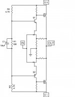
I just skipped the thermistor and installed the resistor. Or don't install the resistor and make R3 and R4 1K.About leaving out those Thermistors .....
When you leave out the temp compensation Thermo (and it's 2k2R resistor), you have to screw the pot down further (reduce it's resistance) to compensate and it's no problem, but ....
- this puts more current thru the small wiper of the pot (usually cermet if it's a multiturn one), and there is a limit to how many mA you can pass thru this for both long life and without deteriorating the sound of the cermet pot (even further- IMO)
...
I've read Vishay's datasheets, where does it say that maximum current is 3mA?
Vishay Precision Group - Foil Resistors
It has been said to use LDRs instear of trimmers. I'm sure Uriah will help us here, won't you?
 Here it goes, what is the maximum current we can pass through the variable resistor element?
I think you are mixing different terms. To make a silent cooling system (my computer is very silent, btw) is different than the automatic integrated fan control that computer motherboards have. Microprocessors have an internal thermomether that tells the motherboard to give more voltage to the fan as heat rises up. So when you are using nearly nothing of the processor power (almost all the time), it runs very very slow. All computers nowdays are implemented this way (you can disable it in the BIOS, though).Regi,
That link about using those quiet cooling system of the CPUs is rather interesting - is the temp controlled by on/off system or variable fan speed? ie, a 130W cooler would run rather slow for a 62W F5 heat input and be nearly totally silent, yes?
The much closer grouping of the o/p Fets to the cooling plate would make thermal tracking so much tighter, smaller pcbs like Peter Daniels ones, quicker heatup times, no big heatsinks or cases, ....
Hmmmmm! Interesting, indeed.
Heatpipes are a great way of quickly delivering heat to other places. See some examples here. It will not be too difficult to hold 4 of these inside a case and attach a mosfet to each one. Install a pot on the outside to control their speed, so you can choose to run a high (I mean HIGH) bias at the trade of more ambient noise. But with higher bias you get more power, so you will hear the fan less

If you add the LDRs idea, and put some pots on the outside to control them and some measurement points, you get an amplifier with selectable bias!!!
The LDRs will allow you to have them near the amplifier circuitry while controling them further away.
VENTILADORES CPU Tienda de Venta online PcComponentes.com
Regiregi 22
I have found your post quite interesting as I am working on similar ideas on my build of the balanced F5
At present to start with the plan is to use 3 parallel mossfet 12 in total for the balanced version the supply is about 28 V and the target is 2 A on each
I am trying out a similar approach with computer fans and noticed that especially the large ones 120 mm are pretty quiet when running at 75% or less of the rated voltage
I am using a LM 317 to obtain a variable voltage this is controlled by a thermistors (the same as in the F5 build) and copper heath spreaders + same very large heath sinks (300X400X83)
I am not ready to post more details, as components values need to be finalised
But hope we can exchange ideas on this.
As I am pushing the envelope (28V X 2A= 56 W dissipation on the mosfet) I am looking for a reliable speaker protection circuit and would appreciate if any body can post same links here.
Tanks
Funny that you should mention that Regi, as i just went looking for more details about the W1260 1/4Watt pots on the Texas Component website but can't find it now at all - sorry - it's there somewhere.
With the LightSpeed LDRs, we know that they do sound good, but not sure if a simple design to act as a trimmer here is feasible - once the stable temp/offset is reached, it doesn't move about much, except at startup.
One of the local CPU cooling whizkids can't see any difficulty getting rid of 60 odd watts via a Prolimatech or CoolerMaster unit without excessive fan noise even tho the fan speed is not low anymore.
If a base plate is used to mount the 2 power fets close together (ie a Peter D pcb) and this then clipped to the cooler plate, no problem - apparently, variable temp/speed control isn't any difficulty.
- we'll see ...
I'm trawling thru the thread to see if this has been sorted before - keep me busy!
...with ordinary heatsink ribbing, I dont see a fan being very optimal
its disturbing the natural convection flow..
My EXPERIENCE is that a fan vastly improves the efficiency of any heatsink.
I recommend this link if you are interested on what makes a fan a low noise fan. On page 2 there's a list with the recommended ones. I have tried Noctua and Nexus, both with excellent results.
Recommended Fans | silentpcreview.com
In that website you can get lots of articles about cooling, passive cooling, all oriented to the PC market.
Another thing I will recommend is to use one of these fan controls for PC. You can get them for less than 10$, and only need any 12v supply.
You have a the simpler 4 fans control,
Cooltek LSK435B Rehobus 3.5" Black LSK435B - Frontal Multifunción
While with this one you can control till 6 fans,
Zalman MFC1 Plus Black - Rheobus 6 Coolers ZM-MFC1 PLUSB - Frontal Multifunción
Or if you want to go high, get one with digital control and integrated thermometers. 29€ is a steal compared with most of the DIY components we buy.
Scythe Kaze Master Ace 5.25" KM02-BK - Frontal Multifunción
For this last one, you can unmount the display and pots from the frame and install them in your custom case, nice idea
Here you can get ideas for other interesting options,
Frontales Oferta en Tienda online buenos precios descuentos
This way, you avoid the problem of different ambient temps in winter and summer. So when the summer comes and your heatsink gets hotter, just turn the pots a quarter
Bksabath, I would be glad in exchanging ideas. I am not sure what to build next (based on F5), but I am tinkering in using a few mosfets in parallel or even going balanced too. Keep us updated with your design
Regarding the LDRs, I am not expecting more stability, but avoiding a pot/trimmer on signal path. The same as using a fixed resistor, but you can change it for bias and DC offset. Does anybody know what is the maximum current the resistor side of the LDR can pass?
If you see the size of a nowadays processor, in this die size we are able to mount 2 mosfets, close together without touching. What I am thinking about is how to hold them in place, drilling is not an option because there are heatpipes inside which will spill the liquid if you do so. We need some kind of clip that makes enough force to avoid falling off.
Regards,
Regi
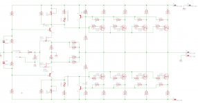
So I just made a schematic for F5 with cascoded input and 4 output pairs.
Used the same schematic from cvillers F5 scaled up with more outputs.
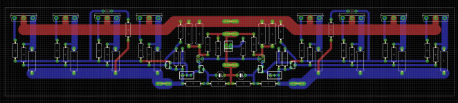
Layout is almost done but wouldnt mind a little input from the fine people on diyaudio.
Before I spend the time with the finishing touches and making gerbers.
But keep it constructive.
Used the same schematic from cvillers F5 scaled up with more outputs.
Layout is almost done but wouldnt mind a little input from the fine people on diyaudio.
Before I spend the time with the finishing touches and making gerbers.
But keep it constructive.
Attachments
Last edited:
this one
Very pretty, though i don't get the point of it.
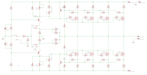
So I just made a schematic for F5 with cascoded input and 4 output pairs.
Used the same schematic from cvillers F5 scaled up with more outputs.
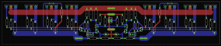
Layout is almost done but wouldnt mind a little input from the fine people on diyaudio.
Before I spend the time with the finishing touches and making gerbers.
But keep it constructive.
Just realised I made an error, reversed drain and source connection on 2SJ74, better get that fixed.
And some other stuff.
Last edited:
- Home
- Amplifiers
- Pass Labs
- F5 power amplifier