Double your choke Henries and plot out that 100mA to 5200mA graph.
So the regulation is good down to 1A or something, but it still does not cover the 0,1 - 5,2A range. A couple of questions:
Does the psu need to hold regulation for the hole range of current draw for being a good F5 supply.
Will the supply voltage rise when the amp draws very little current be malign to the operation of the circuit, or is it possible to use an LC filter even if it falls out of regulation on low current draw.
Attachments
Hi,So the regulation is good down to 1A or something, but it still does not cover the 0,1 - 5,2A range. A couple of questions:
Does the psu need to hold regulation for the hole range of current draw for being a good F5 supply.
Will the supply voltage rise when the amp draws very little current be malign to the operation of the circuit, or is it possible to use an LC filter even if it falls out of regulation on low current draw.
the supply rails start off sending 2.6A of bias current. None of this goes to the load.
If the load asks for 1Apk (8Vpk into 8r0) then one supply increases to 3.1A and the other falls to 2.1A. The difference in current between the two supply rails flows to the load and returns via the speaker lead to Audio Ground.
The difference in supply rail currents = output current = speaker return current. There is a small error here to account for NFB current and Zobel current and imbalance in +ve to -ve quiescent currents, these tend to be in the mA range.
If the minimum current of the well performing PSU is 1A then the rails can drop to 1A and still see nominally the same supply voltage.
2.6 - 1A = 1.6A This is the reduction in supply current of one rail. The other rail will increase it's current to 2.6 + 1.6 = 4.2A.
The output current is 4.2 - 1 A = 3.2Apk.
The amplifier will work perfectly well upto an output current of 3.2Apk.
If the load demands more than that 3.2Apk then the unloaded supply rail will rise due to LC falling out of regulation.
I have no idea what effect this big variation in supply rail voltage would have on the amplifier performance when the F5 tries to meet very high current demand.
BTW,
that 3.2Apk requires a low impedance load. Let's assume you have 4ohm speakers connected. 3.2Apk is about 20W into 4ohms, the top 4dB of output (to a maximum of 50W) will be subject to some kind of supply rail voltage modulation.
Hi,
the supply rails start off sending 2.6A of bias current. None of this goes to the load.
If the load asks for 1Apk (8Vpk into 8r0) then one supply increases to 3.1A and the other falls to 2.1A. The difference in current between the two supply rails flows to the load and returns via the speaker lead to Audio Ground.
The difference in supply rail currents = output current = speaker return current. There is a small error here to account for NFB current and Zobel current and imbalance in +ve to -ve quiescent currents, these tend to be in the mA range.
If the minimum current of the well performing PSU is 1A then the rails can drop to 1A and still see nominally the same supply voltage.
2.6 - 1A = 1.6A This is the reduction in supply current of one rail. The other rail will increase it's current to 2.6 + 1.6 = 4.2A.
The output current is 4.2 - 1 A = 3.2Apk.
The amplifier will work perfectly well upto an output current of 3.2Apk.
If the load demands more than that 3.2Apk then the unloaded supply rail will rise due to LC falling out of regulation.
I have no idea what effect this big variation in supply rail voltage would have on the amplifier performance when the F5 tries to meet very high current demand.
BTW,
that 3.2Apk requires a low impedance load. Let's assume you have 4ohm speakers connected. 3.2Apk is about 20W into 4ohms, the top 4dB of output (to a maximum of 50W) will be subject to some kind of supply rail voltage modulation.
Hi AndrewT. I value your inputs.
I guess that with my speakers that are 6-8Ohms and a very light load in other matters, combined with my low listening levels, it might be a workable psu.
I could start out building an F5 with the tranny I have (25Vac), and then later on change to 18Volt seconday tranny and change the filter into a CLC , which would be a lot more stable in supply voltage for a bigger range of current draw.
then explain why you have decided to increase the bias of the F5 from 1.3A to 2.6A?with my speakers that are 6-8Ohms and a very light load in other matters, combined with my low listening levels,
then explain why you have decided to increase the bias of the F5 from 1.3A to 2.6A?
Because I thought that 1,3A was the bias for one channel, adding up to 2,6 for two. The psu is for both channels.
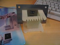
inductor for power supply
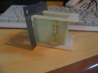
I intend to ask my neighbor who winds transformer as a living to wind an inductor to try out in the CLC the power supply .
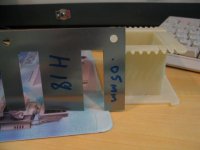
The diameter of the bobbin is 20 cm and the height is 4.7 cm.
WE are going to use 16 g magnet wire and the iron core is made of H 18 --0.05 mm .
I estimate that about 5 metres of the wire can be wound in each bobbin.
I do not have an inductance meter.
Just want to know whether the project is sound in principle ?
Do i need to wind 2 inductors ?
regards
kp93300
I intend to ask my neighbor who winds transformer as a living to wind an inductor to try out in the CLC the power supply .
The diameter of the bobbin is 20 cm and the height is 4.7 cm.
WE are going to use 16 g magnet wire and the iron core is made of H 18 --0.05 mm .
I estimate that about 5 metres of the wire can be wound in each bobbin.
I do not have an inductance meter.
Just want to know whether the project is sound in principle ?
Do i need to wind 2 inductors ?
regards
kp93300
Attachments
Yes, but that can be done without thermistor.
So yes you are right, but the reason a thermistor is used and not just a direct wire connection is to stop audible earth loops with interconnected equipment.
So the complete answer is: A thermistor is used to meet the requirement of "all exposed conductive parts must be connected to Safety Earth". The added benefit of using a thermistor (and not directly connected) is to minimise audible earth loops.
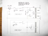
The thermistors on the primary (mains) side of the transformer are to reduce inrush current as Renron stated.
Hopefully this clears everything up.
Thanks for the replies, including from the Master. I do not have twin windings on my Toroid transformer at the primary. It is just one winding for 220v. How do I connect up the Thermistor? Also the way it is shown in the PS schematic, the entire primary current flows through the thermistor isn't it? Am I not getting something here?
Cheers.
You can have a single CL60 thermistor on the live line, it will be enough for your purposes. A 110V connection requires two as the primary current will double.
The thermistor limits inrush current. During steady operation it remains in low resistance mode, as the current at switch-on is pretty high it warms up and its resistance rises (these are PTC, unlike the ones in the amplifier circuit), limiting current through the primary.
Yes, it is is always in the mains path. If that is something you don't like, you can make a small soft-start circuit with a resistor and a relay, and a small handful of parts.
And welcome here, good to see you again")
The thermistor limits inrush current. During steady operation it remains in low resistance mode, as the current at switch-on is pretty high it warms up and its resistance rises (these are PTC, unlike the ones in the amplifier circuit), limiting current through the primary.
Yes, it is is always in the mains path. If that is something you don't like, you can make a small soft-start circuit with a resistor and a relay, and a small handful of parts.
And welcome here, good to see you again
I could have sworn I've seen more amps with PTC protection on the primary, but you're right, the CL60 is NTC. I dug up some older posts by Andrew where he explains the logic of using NTC rather than PTC, I guess you could do it both ways.
The datasheet for CL-60 also shows that you will probably need two CL60 in parallel for 220V as their current capacity drops with voltage, like a solid state device.
The datasheet for CL-60 also shows that you will probably need two CL60 in parallel for 220V as their current capacity drops with voltage, like a solid state device.
Last edited:
I could have sworn I've seen more amps with PTC protection on the primary, but you're right, the CL60 is NTC. I dug up some older posts by Andrew where he explains the logic of using NTC rather than PTC, I guess you could do it both ways.
The datasheet for CL-60 also shows that you will probably need two CL60 in parallel for 220V as their current capacity drops with voltage, like a solid state device.
Thanks Sangram. Nice to catch up with you again though on a different forum.
I have NTC types. I will double the Thermistors for taking more current.
Cheers.
still wrong.The datasheet for CL-60 also shows that you will probably need two CL60 in parallel for 220V as their current capacity drops with voltage, like a solid state device.
220/240Vac needs at least 0ne CL60 in the primary feed.
If you choose to use two CL60 then they must be in series.
Think of it as being the same as the 110/120Vac situation each primary has it's own CL60.
http://www.diyaudio.com/forums/chip-amps/173281-lm3875-speaker-pop-when-powered-3.html#post2299736
You said it yourself, so how does it work? When the voltage doubles, the inrush current through the thermistor should halve?
I use soft starts, but willing to learn
You said it yourself, so how does it work? When the voltage doubles, the inrush current through the thermistor should halve?
I use soft starts, but willing to learn
Not for me, I use square frame transformer, no problem with inrush even with 80000 uF caps per channel/160,000uF total.
I have used soft-start earlier with a mains-rated relay and a resistor, works fine for me. I was more interested from a future reference point of view, as the CL-60 indicates lower load capacity (cap bank) for higher mains voltage in datasheet. I assume this means that two CL60 can be used in series for higher mains voltage with same cap bank?
I have used soft-start earlier with a mains-rated relay and a resistor, works fine for me. I was more interested from a future reference point of view, as the CL-60 indicates lower load capacity (cap bank) for higher mains voltage in datasheet. I assume this means that two CL60 can be used in series for higher mains voltage with same cap bank?
Last edited:
what's VA of your PSU , amount of capacitance , and mains voltage ?
In my case the VA of the transformer is 500VA and the power supply is 220v and the capacitance bank is 60000uF per leg.
Cheers.
- Home
- Amplifiers
- Pass Labs
- F5 power amplifier