Am i mad to use expensive screw terminal caps 7mohms ESR?
I don't think so. Spending $$ on caps is probably more effective than some other things like RCA's or power plugs.
")
Hmm, big caps with screw terminals are very good to use in heavy duty amps
I have also thought that its better to use big sized cans with classA
That the bigger can results in more cool caps, but Im not so sure about that now
With this low voltage you can get quite big capacitance in a smaller package, and a lot cheaper
And besides, tho screw terminals are good for high current they are far from ideal
Maybe also consider if the involved alu and copper oxidate
Im interested in another matter, namely to build the supply caps into their own "housing", inside amp box, to shield them from the worst heat
Hey guys, I'm still having issues on my second set of boards. My one 0.47R power resistor is getting 0.5VDC through it, and as a result smokes when applied to wall power. The bulb limiter dimmed very lightly with just that board connected. The trimpots where all set to 0 (even though they are installed backwards) and this is confirmed from R3/4 at 0.3R.
I'm also receiving 12.4VDC for V- to gnd at the boards, and 14.3 VDC for V+ to gnd at the boards. I thought this was normal, since it adds up to around 24, but after reviewing the schematic it should be +24 and -24. My secondaries on my xfmr are 18V, and i'm using normal bridge rectifiers (which may have gotten effed up when i swapped V- to GND)
Another point to make: with no boards connected the light flashed, dimmed down, and went completely out. With both boards connected it flashed, dimmed down, and then slowly ramped up.
Does anyone know what's going on here?
The bulb in series eats up some of the voltage, so +/-14V sounds reasonable. The behaviour with flashing is also normal as the cap bank draws a lot of current on turn on.
What is the voltage over the other 0.47R? If you have the correct resistors, they do not smoke when 0.5V is applied - there is something fishy about that measurement.
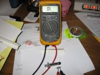
You could post a series of detailed pictures of the amp - this could give us a clue on what might be wrong.
What is the voltage over the other 0.47R? If you have the correct resistors, they do not smoke when 0.5V is applied - there is something fishy about that measurement.
You could post a series of detailed pictures of the amp - this could give us a clue on what might be wrong.
they all read 0.3R, the pots are reversed but they were all the way CCW (technically minimum) does this matter?
No that makes no difference. But if you have them turned down to zero ohm and you get voltage across the resistor anyway, then you have a short somewhere. I good place to start looking is your power fet mounting. You might be running the current directly to chassis gnd.
I play Barry White at my parties, where a couple watts are plenty.
Depends on the track
.... Dat smooth cool baby talk don't need but a few .. then watch out ! ...No that makes no difference. But if you have them turned down to zero ohm and you get voltage across the resistor anyway, then you have a short somewhere. I good place to start looking is your power fet mounting. You might be running the current directly to chassis gnd.
that is a place i have overlooked. i spread some arctic silver compound grease between the heatsink and power fets. So if there was a spot that was metal on metal (no grease) it would be an effective short? I see some of you use thick white insulators-what are these made of? can they be sourced at digikey or mouser?
Dat smooth cool baby talk
All that romantic talk about Barry and Nelson, must be something in the toilet water.
Attachments

@acold7dusta,
If I understand you correctly, you do not use insulators between the powerfets and the heatsink. This is not good.
The drain of the powerfets is connected to the metal tab on the backside of the powerfets. This means you have created an electrical connection between the drains of the powerfets and the heatsink. If your heatsink is connected to ground you have created a short from output to ground.
You should use an electrical isolator that is thermally conductive. You can buy these at the various webshops (mouser et al) or at your local electronics store. Some prefer mica, some use keratherm, silpad and whatnot. The best has the highest thermal conductivity. However if I where you I'd just go to the nearest shop and get what you can to see if that solves the problem.
To clarify why another construction of the same type as you have now might work: Your heatsinks are probably anodised. Anodisation forms an electricly insulating layer which might insulate the drains from the heatsink. This is very unreliable and the smallest scrach will damnage it and create the short from output to ground. Especially if you use an electrically conductive paste such as arctic silver (ie don't use that but use a ceramic variant). For more info about this you could have a look at Rod Elliot's sound pages who has a good article about this stuff: ESP - Heatsink design and transistor mounting
regards,
Joris
@acold7dusta,
If I understand you correctly, you do not use insulators between the powerfets and the heatsink. This is not good.
The drain of the powerfets is connected to the metal tab on the backside of the powerfets. This means you have created an electrical connection between the drains of the powerfets and the heatsink. If your heatsink is connected to ground you have created a short from output to ground.
You should use an electrical isolator that is thermally conductive. You can buy these at the various webshops (mouser et al) or at your local electronics store. Some prefer mica, some use keratherm, silpad and whatnot. The best has the highest thermal conductivity. However if I where you I'd just go to the nearest shop and get what you can to see if that solves the problem.
To clarify why another construction of the same type as you have now might work: Your heatsinks are probably anodised. Anodisation forms an electricly insulating layer which might insulate the drains from the heatsink. This is very unreliable and the smallest scrach will damnage it and create the short from output to ground. Especially if you use an electrically conductive paste such as arctic silver (ie don't use that but use a ceramic variant). For more info about this you could have a look at Rod Elliot's sound pages who has a good article about this stuff: ESP - Heatsink design and transistor mounting
regards,
Joris
Hi jazz,
congrats to your diagnosis & solution!
Cheers,
I am warming up to the F5. I have ordered the 600VA xformer from antek and it should be here monday or so. I ordered 4X33,000 uF caps from mouser and they arrived yesterday. Today I yanked the 22,000 uF caps and put in the new ones.
I also adjusted the bias/dc offset. I am now running about 730mV and +/- 10 mVDC on the outputs. I guess that means about 1.55A. The sinks get pretty hot but manageable.
I am becoming a fan of the F5
I also adjusted the bias/dc offset. I am now running about 730mV and +/- 10 mVDC on the outputs. I guess that means about 1.55A. The sinks get pretty hot but manageable.
I am becoming a fan of the F5
@acold7dusta,
Especially if you use an electrically conductive paste such as arctic silver (ie don't use that but use a ceramic variant).
regards,
Joris
This has been repeated so many times that it is just accepted as fact.
It is WRONG!!!
From Arctic Silver's website,
"Not Electrically Conductive:
Arctic Silver 5 was formulated to conduct heat, not electricity.
(While much safer than electrically conductive silver and copper greases, Arctic Silver 5 should be kept away from electrical traces, pins, and leads. While it is not electrically conductive, the compound is very slightly capacitive and could potentially cause problems if it bridges two close-proximity electrical paths.)
This is NOT the same as being "electrically conductive". Fer cryin' out loud, our RCA cables are capacitive too.
Ron
PS, Please disregard my messy desk
Attachments
Last edited:
- Home
- Amplifiers
- Pass Labs
- F5 power amplifier