I use a 10:1 ratio for radius to thickness for effective heat spread in aluminium.
eg. fins 50mm deep require a minimum thickness at the root of 5mm. They can taper to the outer edge without loosing too much effectiveness. eg, a 6mm to 2mm fin will work almost as well as a 5mm fin even though the tapered fin saves 20% of the volume/weight of the parallel faced fin.
Similarly a 10mm thick backplate will effectively heat up a 200mm diameter (100mm radius from a single heat source) of that backplate and any fins attached within that diameter.
I have found that once you are outside the 10:1 ratio there is a noticeable increase in temperature drop from heat source to distant point of the heatsink.
I have also found that a vertical finned heatsink with the heating device located near the bottom runs the device cooler than the identical heatsink with the heating device located near the top. According to the manufacturers, the optimum height, for a horizontal row of heating devices on a vertical sink is very approximately 40% up from the bottom.
Why Ba-2 instead of F5 ?
Because I have other very nice heatsinks that are perfect fore my F5
Bought them many years ago fore a big classAB project
And the new bigger one fore BA-2, because BA-2 is designed to be a tougher monster F5, so to speak
I think its ok to say that BA-1 and BA-2 deals with all the troubles about building F5 with multiple output devices
And in a very simple way that enables them to be subject fore many possible variations, now and in the future
gaborbela, perhaps you were getting some parasitics? did you move the gate stopper off the board and over to the place where the Mosfet was sitting??
Copper is potentially a problem, as is brass, because of the potential for electrolytic corrosion due to dissimilar metals being in direct contact. If the heatsink is anodized, then no problem, or if you use something like a Bergquist made transfer material between them, but then you lose something over that junction... it would be interesting to see in practice if there was any real difference between a very very flat aluminum to aluminum heatsink junction and a DIY junction of copper to aluminum heatsink (talking the "backer plate" - or "heat spreader")
sharpi31, yes you could use any device that provides effective voltage gain, but if you pick a transformer you have to "like" the sound of the transformer very very much, imho. I think it can have a significant effect on the overall sound. I don't think this amp is much prone to parasitics or oscillations if you use a tight layout like those that are PCB based... so that's not a big consideration.
_-_-bear
DIY junction of copper to aluminum heatsink (talking the "backer plate" - or "heat spreader")
_-_-bear
Thought about using a copper plate 3/8" thick to spread the heat evenly onto the heat sink I have been investigating... Uriah... you hear anything yet from Florida?
Attachments
I still doubt that these are going to handle the heat... maybe 2x the height... maybe...
I'd guess that unless you can make the two surfaces dead flat that ur better off just going direct to the bottom of the center slug. The other problem with a small bit of copper there is that there is a different coefficient of expansion and it may want to act like a bimetallic element, and lift off the surface...
Another problem with this heatsink is that for it to work properly it needs to be very "free air" all the way around. That means if you mount the device as shown, and near the PCboard, there will not be a way for free air flow to occur.
I'd want it free of other surfaces by something greater than 2" maybe 3" or better...
_-_-bear
I still doubt that these are going to handle the heat... maybe 2x the height... maybe...
_-_-bear
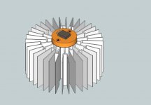
How about somthing like this then... It would be difficult to join together two high.
Attachments
Last edited:
How about somthing like this then... It would be difficult to join together two high.
Cool drawings! What was the reason for using these heatsinks? Was it only availability or do you have some cool plan for the whole chassis?
I think you could potentially make some extremely nice looking amps with those, but in the end, I'm sure it will be much more expensive that ordering some sinks from eg HeatsinkUSA, llc
Do you have a drawing of the complete chassis idea?
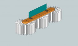
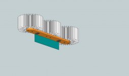
Well I was thinking along the lines of something like this... maybe with three instead of two... I dunno... all I do know is I'll be using the boards I got from you! Thanks for the extra mosfet spacing! These would be two mono blocks.
Attachments
Nice. 
But you need to make sure to get plenty of airflow along the fins.
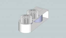
Or you could make a powerhouse like this:
But you need to make sure to get plenty of airflow along the fins.
Or you could make a powerhouse like this:
An externally hosted image should be here but it was not working when we last tested it.
erpii, I think you will need to blow air if you enclose the fins like that.
For natural convection one needs to maximize the airflow, otherwise you have to derate the heatsinks by quite a bit - which means the amp will get too hot, which means the thermistors will cut back the bias, which means it won't be in full class A anymore...
...and I think one might consider putting the board into an "H" configuration... let me try ascii:
O O
| | <---heat spreader "bars"
------ <---pcb
| |
O O <--round heatsinks (not to scale)
EDIT: when I post the spaces get chucked and the drawing squishes left justified - use your imagination??
You could use 3 per line also... and the distance between the heatsinks is only because of ascii drawing...
I dunno...
_-_-bear
Last edited:
I wish I had info to share but they have not got back to me yet. However I have to agree with bear. Airflow may be necessary. I dont think it will need much though. Even a breeze will help A LOT. Computer fans are getting very very quiet. I recently got one for about 4 bucks to waft away solder fumes. Running it on a battery and a pot. I cant hear it at all even two foot from it. I would put them below pointing up. I think it would do it because I think those sinks are less than you need but not far from what you need.
Uriah
Uriah
I wish I had info to share but they have not got back to me yet. However I have to agree with bear. Airflow may be necessary. I dont think it will need much though. Even a breeze will help A LOT. Computer fans are getting very very quiet. I recently got one for about 4 bucks to waft away solder fumes. Running it on a battery and a pot. I cant hear it at all even two foot from it. I would put them below pointing up. I think it would do it because I think those sinks are less than you need but not far from what you need.
Uriah
Agree ! My intention is to run fans also ....
My LR is dead quiet.
I am in the country.
60Hz. transformer hum can seem deafening late at night especially in the winter when there are no bugs to make outside noises.
Fans are problematic. At least have the fan operation controlled by a thermistor for speed control or worst case a thermal switch or two with either resistor or control of the set pin of a 3 pin vreg so that it is quiet until it gets hot...
The quietest fans are "squirrel cage" blowers. You'd want one that is oversized and then run it way below it's intended speed, like crawling around.
I am considering doing just this via something like a clock motor or other very quiet low RPM motor and run the blower via a rubber "O ring" belt for decoupling ... not much breeze is a lot more cooling than natural convection...
_-_-
Hi bear,...other very quiet low RPM motor...
what do you mean?
Maybe something like that:
Scythe Kaze Jyu Slim 1000, 100x100x12mm, 1000rpm, 25.58m³/h, 14.5dB.
Cheers,
Has anyone tried using audio input transformer with F5?I do not know much about audio transformers but my friend said that it is better than using capacitors.I have a laptop that have headphone output.If i use transformer with x3 gain how can it be? Which transformer can i use 10-20$ price range ?thank you
107H Hammond Miniature Epoxy Potted Audio transformer - eBay (item 180398802167 end time Feb-15-10 22:32:28 PST) Is it reliable?
107H Hammond Miniature Epoxy Potted Audio transformer - eBay (item 180398802167 end time Feb-15-10 22:32:28 PST) Is it reliable?
- Home
- Amplifiers
- Pass Labs
- F5 power amplifier