> That's one. I can think of a couple others...
Let me make a fool of myself :
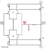
Connect the source of Q1 & Q2 on each (left or right) half together, then connect these two junctions across the two halves with a 10R resistor. The feedback resistors are then 25R and goes from output to the source junction. Non-inverting then.
According to John Curl, this "H" diff pair has very good distortion cancellation.
Patrick
Let me make a fool of myself :
Connect the source of Q1 & Q2 on each (left or right) half together, then connect these two junctions across the two halves with a 10R resistor. The feedback resistors are then 25R and goes from output to the source junction. Non-inverting then.
According to John Curl, this "H" diff pair has very good distortion cancellation.
Patrick
> ......
Let me make a fool of myself :
.......
No , Patrick - that's my job usually ......

I do not have low idss jfet.All of them are above 8ma.Does not them work well ?
They will work very well, but are "over qualified". Keep in mind 2SJ074s are very hard to find nowadays. The F5 has P & N ch jfets at the input so high Idss jfets are not necessary.
GR and lowish BL jfets will work very well too.
I am matching BL jfets and will soon make some available to diyers. Some appear to be in the 6 to 7mA range.
Oh! I am wrong.
Most of signal will be amplified without feedback control.
Thx Wen-san, i understand my mistake now.
It seems there is no way to keep the 2 ways NFB with a symetrical input.
It has to be as follows. But nothing new then.
Attachments
Would be great to have a solution!
I dont´t want to double all components only to test balanced driving.
I was also looking about an hour over the different possibilities, but I am not experienced enough. No clear result.
Thank you bobodioulasso for trying to get the answer!
I dont´t want to double all components only to test balanced driving.
I was also looking about an hour over the different possibilities, but I am not experienced enough. No clear result.
Thank you bobodioulasso for trying to get the answer!
I dont´t want to double all components only to test balanced driving
Neither to have a lot more dissipation.
 Exactly!
So its Showtime for my F5!
I got it hooked up via a 100watt lamp and all seems fine. All the voltages are present, and everything is stable.
I do however measure like 8mV on r12 and r 11 for the bias.
After turning the potmeters for quite some time I suspect something is wrong.
I meseured r3 and r4 and they give about 8 ohms.
Is it possible that I have to turn quite some more (slow pots?)
nope.... powersupply voltage is ok, 24 V positive and negative.
voltage over R3 and R4 is zero.. and over R11 and R12 no change in voltage by turning the potmeter (shows only 6 mV)
voltage meter is connected on both sides of R11 (and R12) parallel over R
this is the same on both channels.
thx for your reply!
voltage over R3 and R4 is zero.. and over R11 and R12 no change in voltage by turning the potmeter (shows only 6 mV)
voltage meter is connected on both sides of R11 (and R12) parallel over R
this is the same on both channels.
thx for your reply!
We (my father and I) suspect that one or more resistors are in the wrong place.
Because turning p1 and p2 leads to nothing more then a measured value of around 8 ohms across r3 and r4.
Probably r3/r4 are of a much lower value then the 2.2k it should be, resulting in such low resistance...
We are in the procces of disasembling the amp and rechecking it. Kinda hard with the Dale resistors to see what is what sigh...
Where I live (Bombay, India) I am unable to get the recommended input Jfets - 2sk170, 2sk370 or 2sj074. Currently I can only get the 2sj108...
Is there any other Jfet pair I could use for the inputs? What are the primary characteristics to look for when trying to source the input Jfets?
~Thanks a lot in advance.
Is there any other Jfet pair I could use for the inputs? What are the primary characteristics to look for when trying to source the input Jfets?
~Thanks a lot in advance.
p1 and p2 have really 5 kOhm? I had once 50 Ohm on a blue one. The inscription was 501 instead of 503. Good luck!
Thanks for all the advise, the pots were 5k ones unfortunately. But on the bright side, we did find out that r 11 and r 12 were of a wrong value (4.7ohm instead of 0.47)
And we found out that alterating turns on the pots, gets the amp to play now!
So one side is luckily working
I guess I should have measured all my components before putting them in... Ah well.. Another valuable lessen learned
I guess I should have measured all my components before putting them in
Thats usually a good idea

Regarding power up with lightbulb
According to Andrew it could mean trouble if one lightbulb blows, due to classA load
It was adviced to adjust F5 into classAB only, with the lightbulb
Confirm that amp is ok
Remove the lightbulbs, and first then adjust it into pure classA
For a gain in the range of 8-12x, what would be the rough range of values for R5&R6 (leaving out R7&R8) and R1&R2? Thanks!
Did you ever find suitable values? I've been playing with the gain as well, and wanted to see if anyone else has some values they've vetted.
the lightbulb is there to prevent a disaster if there is a wiring fault.
Once the wiring has been proved and all modifcations completed the lightbulb should be removed and then the biasing can start.
If the light bulb is still in place when trying to bias an amp then as the bias adjuster is turned up, the bulb reduces the voltage fed to the transformer.
Once the wiring has been proved and all modifcations completed the lightbulb should be removed and then the biasing can start.
If the light bulb is still in place when trying to bias an amp then as the bias adjuster is turned up, the bulb reduces the voltage fed to the transformer.
- Home
- Amplifiers
- Pass Labs
- F5 power amplifier