Heatsink alternative idea
Fyi,
You can homebrew a suitable heatsink, although it does require some metal shop gear to do a clean job (shear & brake - a punch does not hurt either CNC is best but...).
The image shows what i did for my now vintage SE DC coupled Mosfet amp. The caps are 3" diameter, fyi. The power was 35wrms 8 ohms. I figured about 125 watts of heat, the heatsinks got reasonably warm/hot but not more.
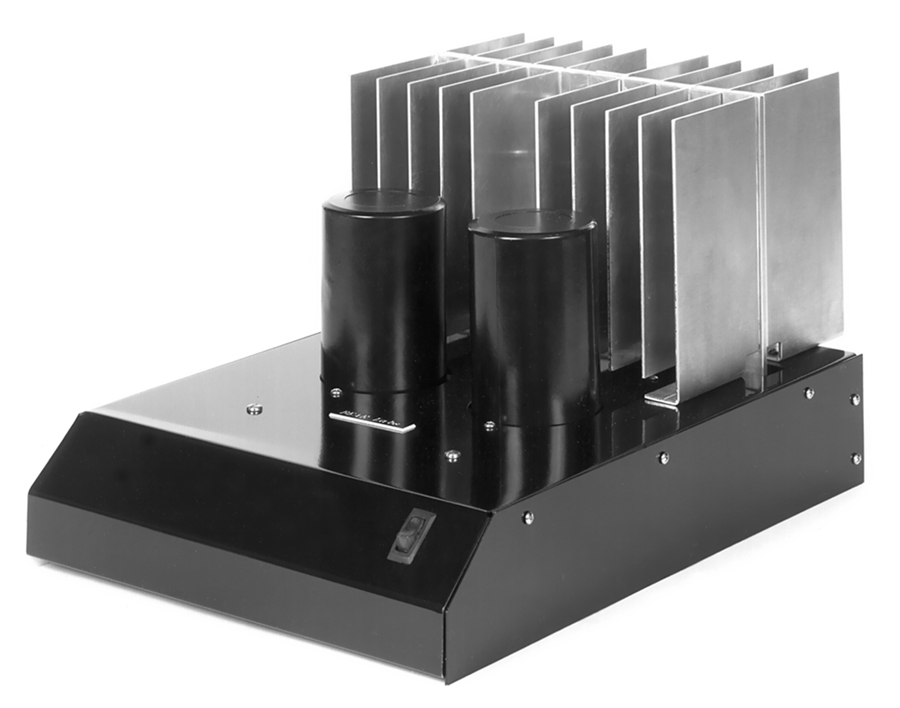
It is another way to go...
_-_-bear
BTW, both Altec and Phase Linear did variations on this theme.
Fyi,
You can homebrew a suitable heatsink, although it does require some metal shop gear to do a clean job (shear & brake - a punch does not hurt either CNC is best but...).
The image shows what i did for my now vintage SE DC coupled Mosfet amp. The caps are 3" diameter, fyi. The power was 35wrms 8 ohms. I figured about 125 watts of heat, the heatsinks got reasonably warm/hot but not more.
It is another way to go...
_-_-bear
BTW, both Altec and Phase Linear did variations on this theme.
Dont forget that Nelson Pass drives his design with higher bias than most, as far as I know
As a rough estimate I would say use heatsink that would fit a 500+ ABwatt
Maybe consider that real hot classA could have much less tolerance in terms of heat changes, and that relative temperature difference between devices and heatsink also is higher
I would think we are easily working above the rated limits of most heatsink specs
And even small changes in environment could have major impact
Last edited:
tinitus, I'll disagree with you on this one.
With a nominal 15w Class A amp there's not much worry about exceeding the capabilities of natural convection heatsinking.
The temp rise vs. power vs. heatsink extrustion profile can be had on any one of the major heatsink supplier's sites. This way you can check your extrusion and see if it is large enough and will support the heat vs. ambient temp.
Clearly if you live in a place like Phoenix Az where the summer daytime temps can exceed 120deg F outside, and possibly more inside (hope you have cooling, but maybe not) then your heatsink considerations are different than folks like moi living in more northern New York State...
So, depending on what you determine as far as the temp rise for your extrusion, you just might want to include a high temp shutoff on the mosfets or nearby on the heatsink.
The other thing to consider is the ability of the heatsink to spread the heat. That will be determined to a great extent by the thickness of the backside of the extrusion (assuming you are using an extrustion, as you see above I did not - partially for this reason). The ability to radiate heat is also a factor determined by the fin size, shape and depth - which for extruded heatsinks has some finite limits due to the extrusion process.
The flatness of the area where the Mosfet meets the heatsink also plays a role, as does the material (if any) that connects the mosfets to the heatsink.
In practice a hotter heatsink might actually be doing a better job than a cooler one - IF the mosfets on the cooler one are hotter!")
_-_-bear
Edit: fwiw Class A bias is Class A bias for any given power level and load it is the same. Pass is no different than any other if it is a straight bias into Class A.
With a nominal 15w Class A amp there's not much worry about exceeding the capabilities of natural convection heatsinking.
The temp rise vs. power vs. heatsink extrustion profile can be had on any one of the major heatsink supplier's sites. This way you can check your extrusion and see if it is large enough and will support the heat vs. ambient temp.
Clearly if you live in a place like Phoenix Az where the summer daytime temps can exceed 120deg F outside, and possibly more inside (hope you have cooling, but maybe not) then your heatsink considerations are different than folks like moi living in more northern New York State...
So, depending on what you determine as far as the temp rise for your extrusion, you just might want to include a high temp shutoff on the mosfets or nearby on the heatsink.
The other thing to consider is the ability of the heatsink to spread the heat. That will be determined to a great extent by the thickness of the backside of the extrusion (assuming you are using an extrustion, as you see above I did not - partially for this reason). The ability to radiate heat is also a factor determined by the fin size, shape and depth - which for extruded heatsinks has some finite limits due to the extrusion process.
The flatness of the area where the Mosfet meets the heatsink also plays a role, as does the material (if any) that connects the mosfets to the heatsink.
In practice a hotter heatsink might actually be doing a better job than a cooler one - IF the mosfets on the cooler one are hotter!
_-_-bear
Edit: fwiw Class A bias is Class A bias for any given power level and load it is the same. Pass is no different than any other if it is a straight bias into Class A.
Last edited:

And a small tubeamp doesnt even need a heatsink, funny eh
Bear, why do you suggest only 15watt ?
But I know Im not wrong, but not saying less wont do
because the F5 is a ~15 watt amp? Or so I have been led to believe...
a small tube amp of the same power using triodes also needs expensive tubes and a very expensive bit of output iron to get in the same range of performance as does this F5. Funny, eh?
_-_-bear
Oh bear, my dear man, this forum is about finding ways around the issues you name
Its really very far from what you believe
btw, F5 is 25watt standard, some try a bit more, and different ways, maybe even higher bias, small mods
And we know papa Nelson support almost whatever we do, as long as it makes sense, and learn
And he keeps teasing with new ideas
Noone ever dared to make trouble in here, at least I haven seen any of that
Thats what its really about, and what also makes Pass forum special
Its about good spirit
Ofcourse its also about being able to build a very fine amp, but really a lot more than that
Man, I sound like an old boring schoolteacher
But its at least expected to have read some Pass articles, more than once
Last edited:
steve and enochRoot, thanks! i need to fix an old back-lit LCD panel on an NAD cd player for a buddy, so i need to place an order anyway.
tinitus,
my heatsinks are like a wood burning stove/chimney. you got me thinking about getting forced air into the heatsink "fire chamber". my front and back plates will have some means of ventilation in the bottom 1/3, and the chimney top will be 75-90% open depending on aesthetic choices for securing the tops of the heatsinks together. i'm wondering what would be a good ratio, focusing on the size of the lower vents vs. the top? i barbecue on a charcoal Weber as well.
tinitus,
my heatsinks are like a wood burning stove/chimney. you got me thinking about getting forced air into the heatsink "fire chamber". my front and back plates will have some means of ventilation in the bottom 1/3, and the chimney top will be 75-90% open depending on aesthetic choices for securing the tops of the heatsinks together. i'm wondering what would be a good ratio, focusing on the size of the lower vents vs. the top? i barbecue on a charcoal Weber as well
.i'm wondering what would be a good ratio, focusing on the size of the lower vents vs. the top?
Hmm, its the top vents that control it all
Think about having all the heat inside the box circulate to leave only at heatsink top
Thats what makes your "forced" convection
If heat can go anywhere else you cant control the flow
Fresh air "intake" comes second, but important too
I like to place part of intake below trafo, and some below heatsink
About dimensioning
I pretty sure its best to focus on the top vents
If they are inadequate the circulation inside box goes into chaos, and convection effect will be less
But ofcourse its a balance act
Last edited:
tinitus, my dear friend... please look at the date I joined and the date that you joined, get back to me on that?
15 watts, 25 watts, what's less than 3dB amongst friends anyhow??
Now let's do the math?
Mr. Pass says to bias the F5 at 1.3 amps. Ohms law says P = I ^2 * R. So, P = 1.3^2 x 8ohms = 13.52 watts
The article states that the amp will deliver more than that into an 8 or 4 ohm load, but clearly no longer in pure Class A, rather in AB.
Thank you.
_-_-bear

isn't it 1.3 amps per device, or 2.6 amps bias per channel?
that's the case for circlotron , where you have two PSUs , but F5 have just one .
1A3 , going from + to - , or vice versa , whatever
tinitus, my dear friend... please look at the date I joined and the date that you joined, get back to me on that?
15 watts, 25 watts, what's less than 3dB amongst friends anyhow??
Now let's do the math?
Mr. Pass says to bias the F5 at 1.3 amps. Ohms law says P = I ^2 * R. So, P = 1.3^2 x 8ohms = 13.52 watts
The article states that the amp will deliver more than that into an 8 or 4 ohm load, but clearly no longer in pure Class A, rather in AB.
Thank you.
_-_-bear
You forgot: a push pull can deliver twice its bias into the load. (Single ended delivers only once)
I max = 2x I bias into the load.
2.6*2.6*8 = 54.08 watts
There are 27 watts pure class A into 8 ohms. (54watts max)
Read the PDF and Zen articles again.
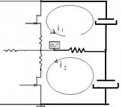
PP Class a amp works like this:
When idle the two halves run equal current: the bias.
Each half runs its current through the load but as they are equal and in opposite direction the load see no current.
When a signal is applied, current varies the same quantity into the two halves but opposite .One side increase while the other decrease.
This variation's amplitude is from bias value to twice this value and then to zero.
When one side is 2xbias, the other side is zero.
This explains why one leaves class A at 2xbias.
Last edited:
the F5 is a push-pull ClassA amplifier that when biased to 1.3A can deliver ~2,6Apk of ClassA current to the load.Now let's do the math?
Mr. Pass says to bias the F5 at 1.3 amps. Ohms law says P = I ^2 * R. So, P = 1.3^2 x 8ohms = 13.52 watts
If the load is 8r0 then the maximum ClassA power is 27W ([2 * 1.3]^2 * 8 / 2)
there is no perhaps about it.being two devices each biased at 1.3amps.
So, to stay in class A the current available has to be constantly 1.3 amps (in this case), IF the current available was 2.6 amps quiescent, then when the amp was driven hard the available current would drop on peaks (as one side neared cutoff). The bias current is quiescent current. One would expect to see a non-linearity (let's assume we removed the feedback which would try to correct for it), which I'm not thinking I have ever seen or seen written about.
Perhaps I am thinking about this incorrectly...
Your description confirms you do not understand how push-pull ClassA operates.
BTW,
27W is equivalent to 54Wpk. i.e. both are 20.8Vpk and 2.6Apk into 8r0.
It is biased at 1.3A, and leaves Class A at 2.6A.
Start at page one
I was thinking about a situation where the amp goes into AB (without feedback) and the Pch and Nch devices do not have curves that perfectly overlap so the area where one goes into cutoff does not track exactly as cutoff is reached, the cutoff is reached and the driven transistor is the transfer curve that continues.
Note to self, good idea: don't post in the AM before being fully awake...
Note to self, good idea: don't post in the AM before being fully awake...
This explains why one leaves class A at 2xbias.
...When one half runs more than 2.6A ,which can be the case with less than 8 ohms loads, or even 8 ohms reactive ones, the other half is cut off. Then that is classAB mode.
Thanks Andrew to repeat what i did just say.
Last edited:
- Home
- Amplifiers
- Pass Labs
- F5 power amplifier