My bad, i meant just the PCS part.
I do recall noticing something of a price rate alteration => http://www.diyaudio.com/forums/grou...group-buy-fqa19n20c-fqa12p20.html#post1494775
I do recall noticing something of a price rate alteration => http://www.diyaudio.com/forums/grou...group-buy-fqa19n20c-fqa12p20.html#post1494775
The irf240 and the irf9240 are not well matched.
I think it hardly matters who makes to non-complementary pairs.
A better match is the irf240 and irf9140 for complements.
The 9140 is a 100V device and this limits the supply rails to <+-50Vdc. No problem for a ClassA amplifier.
I think it hardly matters who makes to non-complementary pairs.
A better match is the irf240 and irf9140 for complements.
The 9140 is a 100V device and this limits the supply rails to <+-50Vdc. No problem for a ClassA amplifier.
> Patrick built it, and it worked, but he didn't seem too impressed with it.
> Which suggests to me that something is not quite right.
I consider this remark misinterpretation and perhaps somewhat misleading.
Firstly the fact that I am currently not using the balanced F5 in my reference system, and that Peter likes his SE version, is not sufficient to draw any conclusion on the relative performance between the two.
I have only built the balanced version, with 2 different types of MOSFETs (Toshiba and Fairchild), and I like the Toshiba more. But it is personal taste. I have NOT built the SE version, so I cannot make any comparison for you.
In general, I only build balanced amplifiers, as they allow cancellation of even harmonics. Some like second harmonics which "sweeten" the sound. I don't. Again personal taste.
I do not recall saying the F5 is a not-good-sounding amp. There are many reasons why I am not using it in my reference system, the most important of which is lack of gain, which I need for my particular setup. On top of that, I have a very high bandwidth system (my power amp is 350kHz bandwidth, 120W Class A), so the additional bandwidth does not bring me any advantage. In someone else's system, it might be.
The fact that I choose another amplifier for my daily use does not make the balanced F5 good or bad. Just as one cannot compare a F5 directly to a F4 or an AXJ. They are all audiophile amplifiers. Which one you might like is, again, your personal choice.
I have optimised the balanced F5 circuit based on the devices I used, and as much as I can tell, the values are closed to optimum. That does not mean that there are no rooms for improvement. But it is unfair to imply there is anything fundamentally wrong with it, just as someone else tried to suggest with my SMD-B1.
In the end, you build the design which appeals to you. Guaranteed results can be had if you should build 100% as Nelson says. I like to experiment and every now and then design my own. And publishing my circuit is no claim to any improvement over the original design. It is just my own implementation that I wish to share. Hopefully someone would also experiment and improve it further, for the benefit of all.
Happy experimenting,
Patrick
Last edited:
Banned
Joined 2002
I wish the aleph mini's were balanced, but then again, id have to go buy a few new goodies to make it work, I guess having balanced is nice, but to make it all work you have to have all the proper equipment.
Ie a balanced pre-amp either balanced out but se in or balanced in and out then you would need a source with balanced in ie cd player or some kinda converter.
I went se because i didn't have to mess around with that stuff, however if i had money and time i would try it with balanced, maybe next year ill build a f5 and try balanced, witch would mean i would have to build all new crosoovers etc etc, see it all adds up.
In personal learning through out life, i weed out certain things, i build amplifiers and stuff for me, not any one else, i learn alot and try alot of things also.
Every one is different every one has their own opinion too, mines beter than yours because ...... no no mines beter because i bought all gold pieces, oh yeah mines better because i spent 30k on cables, nooo mines better etc etc, i now weed out that stuff.
Build it enjoy it tinker with it learn from it")
Ie a balanced pre-amp either balanced out but se in or balanced in and out then you would need a source with balanced in ie cd player or some kinda converter.
I went se because i didn't have to mess around with that stuff, however if i had money and time i would try it with balanced, maybe next year ill build a f5 and try balanced, witch would mean i would have to build all new crosoovers etc etc, see it all adds up.
In personal learning through out life, i weed out certain things, i build amplifiers and stuff for me, not any one else, i learn alot and try alot of things also.
Every one is different every one has their own opinion too, mines beter than yours because ...... no no mines beter because i bought all gold pieces, oh yeah mines better because i spent 30k on cables, nooo mines better etc etc, i now weed out that stuff.
Build it enjoy it tinker with it learn from it
Banned
Joined 2002
My system is balanced from DAC (chip) to power amp.
Patrick
What about pre-amp ?
One additional remark on the difference in the balanced F5 implementations :
> But I didn't implement the output protection circuits (Q4, Q5 in the original schematic) and used identical values for the source resistors (R1,2 =10Ohm, R11,12 = 0.235Ohm) and the feedback resistors (R5,6,7,8 = 100Ohm). The output devices are 2SK1530/2SJ201 from Toshiba.
In my published circuit, which is identical to what I built, I did use different resistor values for the top (2SK170 / 2SJ201) and the bottom (2SJ74 / 2SK1530) halves. This is because while the MOSFETs are perfect complementary devices, the JFETs are not. Using different resistor values would allow gain balancing between the two halves, such as they contribute equally to driving the load, and also allow better harmonic cancellation.
In a balanced system, this cancellation is less important as in SE, as the cancellation will take place again between the left and the right halves, assuming you have (near) perfectly matched devices.
And the reason I run mine at +/-16V, 4A is simply that I have low impedance speakers. As is, you get maximum output power at about 6 ohm. (I always leave 4V Vds as minimum, by design)
Patrick
I consider this remark misinterpretation and perhaps somewhat misleading.
I was hoping it might provoke some discussion on the matter, which it did, so thanks.
Could you comment on whether there should be (or could be) another reference to ground around the feedback loop. This was not omitted on the Aleph JX, though it is a slightly different arrangement from the original.
Last edited:
Good question Thanh about the ground around the feedback loop !!!
If that help please take a look at the Aleph J and the AlephX J .
Also F5 the F5X .
Many differences between the AJ & F5 circuit .
But these question make me curious to .
I just try to get help here to , more people think on the same think we can get probably more idea .
Is not possible to run some simulator test?
Greets
Sounds like the same issue regarding whether to connect cascode resistor directly to ground, or through base resistor, as I recall it
Masters answer was that there is no simple answer and that you have to try both to know which to prefer
My guess is that F5 ground scheme is exstremely simple, or so it seems
I would expect one should be very careful not to disturb this delicate balance
There are no coupling film caps either, which would be to ground
Im sure theres a good reason why not
Hello tinitus
The cascode story out of the table after I decided to go with the X wich would be powered by 24V rail .
For that reason I no longer need cascode .
Our question with Thanh the feedback loop ground .
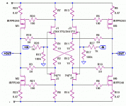
If you take a look the regular F5 the four 100R resistors (R5, R6, R7, R8) is connected to the ground by the two 10R resistors (R1,R2)
Now at the X verizon R1 & R2 cross connected , X-ed .
My question if those resistors still have to be connected to the ground to ???
I think is very important these to be clear !!!
The cascode story out of the table after I decided to go with the X wich would be powered by 24V rail .
For that reason I no longer need cascode .
Our question with Thanh the feedback loop ground .
If you take a look the regular F5 the four 100R resistors (R5, R6, R7, R8) is connected to the ground by the two 10R resistors (R1,R2)
Now at the X verizon R1 & R2 cross connected , X-ed .
My question if those resistors still have to be connected to the ground to ???
I think is very important these to be clear !!!
Sorry I forget to attach the schematic , that would make easier to understand our question .
If you look at the red box there is a ground connection .
Do I have to use that ground at the X verizon???
These is my last question , if I will know the answer I can go on to each the PC boards .
PLEASE IF SOMEONE KNOW THE RIGHT ANSWER LET US KNOW ,please help with these . Thank you very much !!
Greets
Attachments
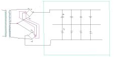
I have a heavy duty Semikron 100A bridge probably I will use that .
In my Aleph X works well . And the quality not bad either . Also your drawing is OK .
I did com paired these bridge with a couple another type bridge , I like these better .
My opinion about the ground question we not supposed to connect the X to the ground at least not that way how is connected in the reg.F5 . It would be shorted the X .
But I hope I get some answer from some expert guy . Because the feedback at the F5 is connected to the ground by the 2 10R resistors .
Greets
Attachments
I think it was answered before
Balanced input has a pos and neg AND a ground
You may say that the usual ground on a "single ended" is changed to a hot negative
Ground on a balanced is different from ground on a single ended
Probably not right either, but whatever
Also bare in mind that F5 is a ready to go design
And in its commercial form should work flawlessly anywhere in the world, with all sorts of strange gears connected
Could be its just a precaution against noise issues
Anyway, either of them are supposed to work as is
Just choose the one you like and build it
btw, I have just been told that my coming heatsinks weigh in at 25kg
That heatsink more than enough , specially for SE type F5 . You wrote if I remember well your max power supp. it will be around 26-28V rail.
I think I go on and I each the boards .
After I will found out what is the best solution about those questions I still have . I will use a low voltage transformer to power it up , to get some experience with the bias and offset .
Of course right now the X is my only plan .
Greets
I think I go on and I each the boards .
After I will found out what is the best solution about those questions I still have . I will use a low voltage transformer to power it up , to get some experience with the bias and offset .
Of course right now the X is my only plan .
Greets
- Home
- Amplifiers
- Pass Labs
- F5 power amplifier