Please, don't write about things you know didley squat about. That tends to discourage people who are willing to learn something new.... with Lateral mosfet F5 does not working !!
You may present your own experience, like: "I didn't have success with lateral mosfets in F5"
Laterals have different pinout, different Vgs, different transconductance, tempco, etc... But when you are aware of those differences and adapt the circuit/PCB properly, laterals work very nice in F5.
Dear Juma
If you read my post after after that I did corrected myself .
I knew only someone tried with out success right at the beginning .
But after I was informed there are some amplifier built with Laterals . So I said if is OK please go on and build it .
Sorry I was misinformed . But after I got the right information I did corrected myself .
So please forgive me , I would delete the post but I can't .
I did my best I wrote if is working please go on and build it .Actually I like the sound of (a good lateral better )
Greetings
I dont see why 7A pr device would be a problem when we use 3 or 4 outputs pair
I think the major reason we want the laterals are fore easier drive of multiple outputs with the single Jfet, and cascode
I suppose its the doing of low Vgs
Mine have 0.5-0.8 NPN,PNP respectively
Is that what also makes it heat faster
And maybe thats also what makes it slightly more "nervous" at higher bias
And all this would mean that generous heatsinks are important
With multiple poutput and optimal heat transfer, case temperature will be closer to heatsink temperature
To me its not about which sounds better
I expect better sound to come from better function
btw, I got a better price on 1meter heatsink with possible 0.2k/W , which I expect will keep it perfectly cool, and base will be milled planed fore optimised cooling, and I have the keratherm isolators
Last edited:
What I wanted to write with out modify the circuit it does not work.
Actually you right .
Sorry one more time .
I know these can cause some confuse , it happaned with me also .
Lineup wrote in another post the Toshiba 2SK1529 /2SJ200 Lateral mosfet .I purchased for a couple hundred Dollars (15 pair -$17 each) and after people inform me that is not lateral mosfet .
Now I know even with lateral mosfet will work with the right mod...
Thanks for pointing that out, bobodioulasso!
I guess I'll stick with the plan B, wire the transformer for 220v and plug it in 110, and have a center tapped 33v secondary, albeit at half the power rating. The transformer is specced at 800VA I think, so it's still plenty. Thanks again!
I guess I'll stick with the plan B, wire the transformer for 220v and plug it in 110, and have a center tapped 33v secondary, albeit at half the power rating. The transformer is specced at 800VA I think, so it's still plenty. Thanks again!
What I wanted to write with out modify the circuit it does not work.
I suspected that
But sounds to me like your mistaken again
Its exactly without mods it actually should work
With that I mean to use the thermistors and current limiter curcuit as pr original
The reports about issues have all been with modified curcuit
Which means raised bias, and maybe slightly higher voltage
And also without thermistors and current limiter
In manual Nelson specify heatsinks with 0.6 K/W which isnt that much
But frrom experience he also suggest about 6" x 8", TWO pr channel
And a power supply capeable of continious 6amp, and more than 10amp peak pr channel
Thats fore an optimal or maybe conservative build
Its been stated and proven that less will work perfectly fine
But only fore original with no changes
With the changes we have been talking about, raised bias etc., I think it would be wise not to go cheap on these matters
I could suspect that may have been the case fore some of those who have experienced heating problems
Or maybe unknown issues with heat transfer
Last edited:
Please, don't write about things you know didley squat about. That tends to discourage people who are willing to learn something new.
You may present your own experience, like: "I didn't have success with lateral mosfets in F5"
Laterals have different pinout, different Vgs, different transconductance, tempco, etc... But when you are aware of those differences and adapt the circuit/PCB properly, laterals work very nice in F5.
These is JUMA statement on the laterals !
All I can say I agree with these statement .
One more time if I knew F5 works with laterals I have 10 pair orig Hitachi I'd rather use them than the Toshiba verticals .
Please feel free if you have the right information and use laterals .
It was proven it can be done .Please go for it !
The reason I was touch with these problem when I was mislead by someone , I spent over $600 on Toshiba mosfet . I purchased as they laterals and after I get the right info those are vertical mosfet(s)
I could not return to the store , thank God I can use them in these project !
Greets
You allowed to be misled because you were too lazy to learn how to read datasheets, right ?... I was mislead by someone ...
")
Pre run with cheaper IR devices
As said, I was lucky to get hold of 8 pair of selected Renesas J162/k1058
I would really hate to see them burn
So, I consider to mount a single pair of cheaper IR devices on first powerup
Just with lowish bias
Just to confirm everything is working ok, before mounting the Renesas
It will be fairly easy as I will do it hardwired
Ehh, might be much easier to mount the Renesas without connecting them, and just drill the exstra holes fore the trial IR devices
Any problem with this, maybe in terms of statics ?
Last edited:
#1
lineup
diyAudio Member
Join Date: Dec 2005
Location: the north 10 Watt Single End, JFET input - Lateral N-MOSFET output
--------------------------------------------------------------------------------
hi
Daniel Petrov from Sofia part of Bulgaria
is know at this forum widowmaker - profile
for his Death of Gainclone - DoGC amplifier
DoGC uses a clever and unusual output idea.
See separate topic, with discussion to try figure out how that one works ...
Today, I found another of his creations.
In a Bulgarian forum Daniel started a topic 2007-03-27 ( 27th of March )
Link:
Еднотактен клас А с полеваци
It is a 10 Watt Single End, JFET input - Lateral N-MOSFET output amplifier.
As can be seen in my attached schematic
it features very good, but still not hard-to-find transistors:
- 2SK389BL .... hifi low noise jfet for input - paralleled for 12 mA in first stage
- TL431, BC550C, BC639 for good Output Class A bias control and PSRR (supply insensitivity)
- Two 2SK1529 Lateral MOSFET for Output Stage
- No global feedback from output to input stage
-------------------------------------------------------------------------------------
2SK1529 is a Toshiba Lateral MOS of same series as 2SK1058.
But with a bit higher power:
- 2SK1058, rated 07A, 100Watt
- 2SK1529, rated 10A, 120 Watt
See amplabs.com POWER MOSFET data: Audio Power Mosfets - Buy OnLine @ AmpsLab
Here below is is the attachment of this nice
- True Class A
- Single END
- ZERO global Feedback
- Toshiba Lateral MOSFET output
- 10 Watt
- Easy to build Power Amplifier
- Separated input-output power supply
- CLC filtered supply, a la Nelson Pass
Regards
lineup
------------------------------------------------------------------------
Hello
Thank you , that punch under the belt a bit .
You guys write always to listen to a expert guys , take advise from them. So I did it .It was Lineup who wrote those Toshiba mosfet(s) are laterals .
Even today He say that .
Also I wrote I'm not a engineer or technician , I learn all DIY "hands on", I read the forum or I ask for advise from guys like you !
From the data not always easy (to me) to know if they are laterals or vertical .
It was a long topic in another tread exactly about these Toshiba mosfet(s), ended up with a disagreement . If is so easy to know from the data those are lateral or vertical I think the expert guys would agree on the fact easily .
The reason when I post a mistake I correct it and I'm never ashamed to write sorry about .
Sorry but I have to write there are hundreds of DIY people we depend guys like you JUMA .
We also like to build our amplifier .You know that well .
Any way you help me with the cascode and I greatly appreseate it .
A very big thank you to you for that !!!
Greets
lineup
diyAudio Member
Join Date: Dec 2005
Location: the north 10 Watt Single End, JFET input - Lateral N-MOSFET output
--------------------------------------------------------------------------------
hi
Daniel Petrov from Sofia part of Bulgaria
is know at this forum widowmaker - profile
for his Death of Gainclone - DoGC amplifier
DoGC uses a clever and unusual output idea.
See separate topic, with discussion to try figure out how that one works ...
Today, I found another of his creations.
In a Bulgarian forum Daniel started a topic 2007-03-27 ( 27th of March )
Link:
Еднотактен клас А с полеваци
It is a 10 Watt Single End, JFET input - Lateral N-MOSFET output amplifier.
As can be seen in my attached schematic
it features very good, but still not hard-to-find transistors:
- 2SK389BL .... hifi low noise jfet for input - paralleled for 12 mA in first stage
- TL431, BC550C, BC639 for good Output Class A bias control and PSRR (supply insensitivity)
- Two 2SK1529 Lateral MOSFET for Output Stage
- No global feedback from output to input stage
-------------------------------------------------------------------------------------
2SK1529 is a Toshiba Lateral MOS of same series as 2SK1058.
But with a bit higher power:
- 2SK1058, rated 07A, 100Watt
- 2SK1529, rated 10A, 120 Watt
See amplabs.com POWER MOSFET data: Audio Power Mosfets - Buy OnLine @ AmpsLab
Here below is is the attachment of this nice
- True Class A
- Single END
- ZERO global Feedback
- Toshiba Lateral MOSFET output
- 10 Watt
- Easy to build Power Amplifier
- Separated input-output power supply
- CLC filtered supply, a la Nelson Pass
Regards
lineup
------------------------------------------------------------------------
Hello
Thank you , that punch under the belt a bit .
You guys write always to listen to a expert guys , take advise from them. So I did it .It was Lineup who wrote those Toshiba mosfet(s) are laterals .
Even today He say that .
Also I wrote I'm not a engineer or technician , I learn all DIY "hands on", I read the forum or I ask for advise from guys like you !
From the data not always easy (to me) to know if they are laterals or vertical .
It was a long topic in another tread exactly about these Toshiba mosfet(s), ended up with a disagreement . If is so easy to know from the data those are lateral or vertical I think the expert guys would agree on the fact easily .
The reason when I post a mistake I correct it and I'm never ashamed to write sorry about .
Sorry but I have to write there are hundreds of DIY people we depend guys like you JUMA .
We also like to build our amplifier .You know that well .
Any way you help me with the cascode and I greatly appreseate it .
A very big thank you to you for that !!!
Greets
Any way you help me with the cascode and I greatly appreseate it .
Start reading
A major part of last posts here have been about cascoding F5
All you need to know is here, not very long back
read first, ask afterwards
And please, try not to pollute the thread with long non relevant quotes like the one you did on lineup, please
Or at least edit out the whats not important
Its difficult enough to keep track of things as is
Last edited:
Issue with thermistors
Or should I better say, with no thermistors
Say, if someone did a 40watt, with classA bias up to 20watt
Multiple outputs and cascode input
We have heard more than once that above a certain biasing some non IR outputs may get a bit nervous, and run hot, without the thermistors
Or maybe better said, bias gets unstable,as I understand it
Above described 40watt, with lowish bias should not have such problems
Or maybe just until the output exceeds the 20watt classA
What really happens when it goes into classAB above its 20watt classA biasing
Will this amp show problems with bias stability, when driven hard and goes into classAB
This could make me think that it might best to keep the thermistors with such design
I mean, it is a very simple curcuit, and all we have to stabilise bias is the thermistors
Or the neat current limiter
Maybe its time to reconsider it, with proper adjustments
And maybe NOT use higher voltage than makes a full classA drive possible
Yeah, we may have approached this several times before
Just thinking loud to clear my head
But any response would be nice
F5 really seems to be a very finely calculated balance act, and really isnt designed to do what we may try to push it into
Maybe we should be more careful in what we do
It started out with trying higher bias to improve on low impedance drive
Multiple outputs etc
Now its raised supply rails
Yeah, we are "the greedy boyz"
Maybe we will learn it the hard way
With smoke
Last edited:

my F5 adventures
Hi,
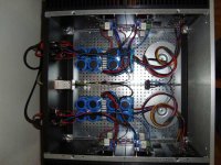
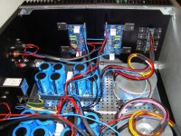
after listening for around 4 month or so to this wunderful amp I think it's time to post some technical details and of course some pictures.
My actual F5 is based on EUVL's balanced F5 posted here:
http://www.diyaudio.com/forums/1542055-post1216.html
But I didn't implement the output protection circuits (Q4, Q5 in the original schematic) and used identical values for the source resistors (R1,2 =10Ohm, R11,12 = 0.235Ohm) and the feedback resistors (R5,6,7,8 = 100Ohm). The output devices are 2SK1530/2SJ201 from Toshiba.
The bias current is set to 1.6A. Unfortunately, the rail voltages differs between the right and left channel (left: 2x12Vac -> +/-14Vdc, right: 2x15Vac -> +/-18Vdc) and the toroids are a bit small for such an class A amp, they are rated only at 250VA. I've ordered new ones rated at 400VA.
It's built up with cviller's boards for the amp channels and power supplies, and boards from Peter Daniel for the rectifier bridges. The enclousure is from Hifi2000 (Pesante Dissipante 05/400).
Here are some pictures:
Hi,
after listening for around 4 month or so to this wunderful amp I think it's time to post some technical details and of course some pictures.
My actual F5 is based on EUVL's balanced F5 posted here:
http://www.diyaudio.com/forums/1542055-post1216.html
But I didn't implement the output protection circuits (Q4, Q5 in the original schematic) and used identical values for the source resistors (R1,2 =10Ohm, R11,12 = 0.235Ohm) and the feedback resistors (R5,6,7,8 = 100Ohm). The output devices are 2SK1530/2SJ201 from Toshiba.
The bias current is set to 1.6A. Unfortunately, the rail voltages differs between the right and left channel (left: 2x12Vac -> +/-14Vdc, right: 2x15Vac -> +/-18Vdc) and the toroids are a bit small for such an class A amp, they are rated only at 250VA. I've ordered new ones rated at 400VA.
It's built up with cviller's boards for the amp channels and power supplies, and boards from Peter Daniel for the rectifier bridges. The enclousure is from Hifi2000 (Pesante Dissipante 05/400).
Here are some pictures:
Attachments
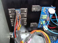
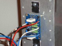
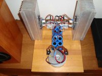
my F5 adventures (cont.)
Before building my actual balanced F5 I set up an original one, it was something like an "engineering sample" and useful to play around with bias current, supply voltages, etc.
For this version I used the boards from Peter Daniel because they fitted better to the heatsinks I had.
Again some some pictures:
Attachments
- Home
- Amplifiers
- Pass Labs
- F5 power amplifier