this seems to confirm that the limiter was triggering on a valid audio signal into a valid speaker load.................and off went current limiting circuitry: the amp opened up and instead of boring became much more interesting and involving, to a point that I spent whole evening listening to it
The earlier discussion, that I contributed to, came to a tentative conclusion that the limiter was set too low for 8ohm speakers.
6ohm and 4ohm speakers would fair even worse.
Very reactive speakers would require an even higher setting for the limiter.
Try doubling the triggering current level and re-assess whether it makes an audible difference.
The sound quality may benefit the if the limiter current were trebled or even quadrupled.
Last edited:
In real life
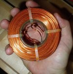
Picture of a 2.7mH/10AWG aircoil, weighs in at +4lbs.
Costs about $115 overhere, roughly 80% of a comparable thingy at North Creek.
(either that, or it's actually tiny and i'm a midget in real life instead of a ftbstrd)
Attachments
(either that, or it's actually tiny and i'm a midget in real life instead of a ftbstrd)
Dream on Dutchy whale

Anyhow, the pic is a bit deceptive.
A wild guess says that the inductor Jaccolina is holding, is on the wrong side of 100mm wide.
Size is most likely going to be the limit of what most here are willing to do.
Magura
$63.95 each for 2 of these from Madisound:
An externally hosted image should be here but it was not working when we last tested it.
$63.95 each for 2 of these from Madisound:
An externally hosted image should be here but it was not working when we last tested it.
They don't sport a data-sheet, so I don't know this for sure, but the foil inductors I've come across so far, were made for x-overs, as the insulation (often PP or the like) isn't going to survive the core temp, in a power app.
Magura
In Post# 2814 Peter Daniel says:
When I listened to F5 first time, I thought pretty good, but probably not good enough to replace GC, another wasted effort
Then I thought why not removing all the parts that are not really needed and off went current limiting circuitry: the amp opened up and instead of boring became much more interesting and involving, to a point that I spent whole evening listening to it.
So a chip amp is better than the F5 because it has current limiting? I don't know about that. I wouldn't think the current limiting would make that much difference. The reviews of the F5 certainly don't reflect that opinion.
In Post# 2814 Peter Daniel says:
Thank you

labjr, Im with you on that one, to dont take anything fore granted
I dont dare mention anything commercial
Probably also system related
So, nothing conclusive yet, whether to power limit or not to power limit
Hi Renron
How is your F5 doing
I have read a paper carefully explaining why NOT to use supply chokes in SS amps
Cant remember the issue
Cant find the paper, but found these
http://www.qsl.net/i0jx/supply.html
http://www.tpub.com/content/neets/14179/css/14179_193.htm
I once tried to insert a speaker xo inductor in a small supply, and trafo buzzed like mad
It was 100% quiet without
I have no idea why
Last edited:
I would be suspicious looking at the price. At that cost, it is unlikely to be respectable quality magnet wire, that it's made of.
For a cross-over, I wouldn't hesitate using that sort of questionable quality, as the power involved is a fraction of that in the CLC filter.
Magura
Hi Magura,
How would the quality of it affect the CLC filter?
Next, actually my plan is 4mH-->44mF-->0.1ohm-->40mF,will this avoid some of the problems mentioned earlier?
Hi Bobo,
I am not referring to +- 24 but +48VDC-0VDC into F5 circuit.Will it work?
I fear not to understand exactly what you mean.
Hi Bobo,I meant using a 48vdc into F5's +24VDC and tie the -24VDC terminal of the schematic to gnd.
Try doubling the triggering current level and re-assess whether it makes an audible difference.
The sound quality may benefit the if the limiter current were trebled or even quadrupled.
Thanks Andrew, but how
Dont know, but could the issue with chokes be that its not so good with "low" voltage, and high current
Last edited:
Tinitus,
After killing a couple of transistors myself, (a sad death due to my hooking up the PS incorrectly) I have asked for help in troubleshooting my F5. Steve Eddy has graciously offered his expertize in diagnosing my errors. Got a call from him last night, and one channel is up and running.
After hearing how Very, Very Smooth it sounds at "Burning Amp 3" I am anxious to have it come back home and power my curved Thors.
So, in answer to your question; it's comming along slowly. I'll post a photo when its completed.
Thanks Tinitus,
Ron
Hi Bobo,I meant using a 48vdc into F5's +24VDC and tie the -24VDC terminal of the schematic to gnd.
It will work if you first create a 0 volts point using serial connected caps such as in the Quad arrangement, and add a third cap across all this for filtering reasons.
My mains voltage is low as well, turning on my PC on the other side of the room brings my rails down to +-17. I may need to add some headroom and do regulated.
It seems like the wiring in your house is very long or is under rated or maybe it is corroded if it is an old house.
You could run a new separate mains line to the power point your amplifier is using with very thick mains cable. That would also help.
However it does look like a new transformer is on the cards.
Last edited:
is your mains supply voltage consistently low?
Is it within the specification limits set for the supplier?
What is the voltage of your transformer? mains input voltage, secondary output voltage? What is the VA and regulation of the transformer?
What capacitance are you using in the PSU?
How many channels are you running from the PSU?
Do not go to a regulated supply yet. Get the present one working properly.
If it were for me I would say NEVER go regulated for a ClassA amplifier.
This is killing me - third time I have replied to this and had it dissappear due to my flaky network.
supply voltage is around 104-109 volts AC. It is consistantly low, but varies greatly with load in the house. FPL says it is ok.
The transformer is an Antek 4218 400VAC 18-0-18 Toroidial transfomer. It should be able to source 22 amps and stay above 18 volts per secondary according to Antek.
The PSU started out exactly as per the Pass Schematic. 22mfd/4x.47ohm/22mfd per rail. I added another 2x.47ohm per rail to get the voltaqe up a bit and resistor heat down. I added another 15mfd per rail (clean side) to get the ripple back down.
I am running 2 channels from this PSU. I am tempted to go to a 20-0-20 or 22-0-22 transformer to get the voltage up, but am worried that it will be too high I move the amp.
but varies greatly with load in the house. FPL says it is ok.
Ehhh, doesnt sound safe
I dont say there is a problem
Only saying there could be
I had a wire that got pretty hot, because it wasnt fit to pull the load I put on it
Too long and too thin
Dangerous stuff
I am using Antek 3218, 1 ea in dual mono's and have the same issue. Normal line voltage though. Got a little worse with CLC. Still plenty of snap @17V in my system.The transformer is an Antek 4218 400VAC 18-0-18 Toroidial transfomer. It should be able to source 22 amps and stay above 18 volts per secondary according to Antek.
You don't have to change anything really.
Just build it standard using your 3 output pairs.
I didn't have any issues. It performs flawlessy.
I left out the current limiting circuit, and also the thermistors.
I had no problem with dc offset or biasing. However I did match all of the devices.
Ah, I see, it was you who was helpful to post schematic, some time ago (post 4153)
You have resistors in supply line to input Jfets
550ohm in positive rail and 440ohm on negative side

Ehh, bias adjustment maybe ?
Last edited:
- Home
- Amplifiers
- Pass Labs
- F5 power amplifier