1. Well, which is source resistor? R11 and R12 in your sch
3. Cap on feedback loop resistor, which is that? How big a cap? R6 to 8 in your sch. Few pF to be checked with instruments
5. Power resistors between supply line and power transistors. Why only 3watt resistors? Many R in // give you an higher wattage one (and lower the resistance) I.E. 4 x 0.47 Ohm/3 W = aprox 0.12 Ohm/12 W
Other people could explain better than me anyway
Last edited:
Good to know - these kind of answers remain buried in the thread and it is foolish to repeat questions, as I was about to post a similar one.
Since the feedback resistor is pretty small (it's the 2x100 ohm resistors in || from output to the source of the input jfets, caps will require on both these), the cap would be large-ish - around 1nf or so would be a starting value - however this is probably required only if oscillation rears its head.
I have another question: For output jfets with worse capacitance (say, IRFP540/9540) and parallelling them, would the gate resistor be higher in value? Say 220 ohms for each output device.
R11/12 dissipate around 800mW each (1.3^2*0.47). 3 watt resistors seem sufficient. For any changes I guess one would calculate the required wattage themselves.
You don't have to change anything really.
Just build it standard using your 3 output pairs.
I didn't have any issues. It performs flawlessy.
I left out the current limiting circuit, and also the thermistors.
I had no problem with dc offset or biasing. However I did match all of the devices.
Just build it standard using your 3 output pairs.
I didn't have any issues. It performs flawlessy.
I left out the current limiting circuit, and also the thermistors.
I had no problem with dc offset or biasing. However I did match all of the devices.
Y
I left out the current limiting circuit, and also the thermistors.
Sure is simpler that way
I understand the thermistors, sort of
What is Q5/Q6 doing ?
How much is the limiting factor in reality ?
What is the power limits without the limiting curcuit? low impedance? loud SPL? or both?
Does it sound better without current limiter ?
Hi cbrworm.
I am guessing you used crc in the power supply. If you want to up the voltage without the need for a new transformer then remove the resistors.
I did do CRC, the voltage is too low right out of the rectifiers. I lowered the resistance, but when I bypassed the resistors completely I got a faint 120hz hum at about -67db.
My mains voltage is low as well, turning on my PC on the other side of the room brings my rails down to +-17. I may need to add some headroom and do regulated.
I think $25 is expensive for 1.44lb of enameled copper wire.I would be suspicious looking at the price. At that cost, it is unlikely to be respectable quality magnet wire, that it's made of.
For a cross-over, I wouldn't hesitate using that sort of questionable quality, as the power involved is a fraction of that in the CLC filter.
Magura
There is more than sufficient margin in there for manufacturing cost from good quality materials.
The 2mH, 1.63mm diameter and 0r3 along with the dimensions confirm this is properly sized for a bias current of 1.3A. Pd~500mW.
A pair of channels from a shared inductor would still have to dissipate just 2W for 2.6A of bias.
I think $25 is expensive for 1.44lb of enameled copper wire.
There is more than sufficient margin in there for manufacturing cost from good quality materials.
That you don't know, and have no intention to check up on the facts, that's fine with me, but just don't pass ignorance as knowledge.
Magura
is your mains supply voltage consistently low?My mains voltage is low as well, turning on my PC on the other side of the room brings my rails down to +-17. I may need to add some headroom and do regulated.
Is it within the specification limits set for the supplier?
What is the voltage of your transformer? mains input voltage, secondary output voltage? What is the VA and regulation of the transformer?
What capacitance are you using in the PSU?
How many channels are you running from the PSU?
Do not go to a regulated supply yet. Get the present one working properly.
If it were for me I would say NEVER go regulated for a ClassA amplifier.
I have bought many kg of enameled copper wire here in the UK.you don't know, and have no intention to check up on the facts, that's fine with me, but just don't pass ignorance as knowledge.
I know the retail price of enamled copper wire and I would never deliberately try to mislead anyone, not even you.
I would never deliberately try to mislead anyone, not even you.
Then check up on the facts.
Grade A copper from a respectable manufacturer (Synflex and the like), is on the wrong side of 10$ /kg (which btw is fairly cheap, compared to just a year ago), so just the cost of copper will end up on the wrong side of 25$ in retail. Add winding, shipping, handling, and so forth.
Now tell me where they're gonna save some cash, in order to make room for anything but the cost of the magnet wire? Could it possibly be, that the magnet wire is not exactly the best possible quality?
So yes, when an inductor that weighs in at 0.75kg,, is sold in retail for 25$ something is most likely not right.
Magura
Fet Heat
I just got a meter with a temp probe. First using silica pads, the tab temp of the Fet were 80-83c. I switched to Mica and grease and I am now measuring in the 60-65C range on the tab. Is this acceptable?
What is a safe temp for the fet to be running if I am looking for longterm dependability?
Thanks, Nick
Quality Inductors
North Creek winds a nice inductor that uses high quality wire from 16-8g. I have purchase a few for crossovers they do not disappoint. Here is the price list but it's really only a guide. Email or call and they will give you the current pricing.
http://www.northcreekmusic.com/NorthCreekCoilPrices.pdf
You will see quoted that every 10 degree increase in device temperature HALVES mean time between failure. At room temperature a transistor is expected to live 50 years -- go figure.What is a safe temp for the fet to be running if I am looking for longterm dependability?
Thanks, Nick
1.44lb~0.65kg. @ $10/kg that is $6.50 for the copper leaving a mark up of 280% to cover the manufacturing and packaging costs.copper ....... is on the wrong side of 10$ /kg when an inductor that weighs in at 0.75kg,, is sold in retail for 25$ something is most likely not right.
$25 still seems expensive.
In the UK, scientific wire sell 1.6mm enameled copper for just over £10/kg ready wound on a reel. Why bother rewinding it?
This is an inductor to create a slope in the low pass filter of a PSU, 1% precision is not required. +100% -50% would get us in the ballpark
Last edited:
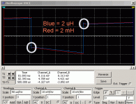
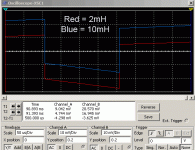
I simmed it with some better (0.05 ohm Panasonic ECG) transistors. Indeed the 2mH inductor reduces the ringing occasioned by the parallel banks of capacitors -- I would like to try it out in real life...
Thanks for your sims! Yeah, the ringing appears because there is hardly any filtering with the 2uH choke.
How about showing a sim of the rail noise from charge current with a constant draw of 2.6A? - I think that would very relevant in the choke discussion.
For reference you could even show the CRC performance too.
Does it sound better without current limiter ?
In Post# 2814 Peter Daniel says:
When I listened to F5 first time, I thought pretty good, but probably not good enough to replace GC, another wasted effort
Then I thought why not removing all the parts that are not really needed and off went current limiting circuitry: the amp opened up and instead of boring became much more interesting and involving, to a point that I spent whole evening listening to it.
===================================
Just remember, without the current limiter, if you accidentally short your speaker cable when connecting, then your outputs will probably go poof!
Last edited:
- Home
- Amplifiers
- Pass Labs
- F5 power amplifier

