That's how it is. It has one advantage in that the transformer is
less likely to see some saturation when the two rails do not draw
equal current, which makes it mechanically quieter.
😎
less likely to see some saturation when the two rails do not draw
equal current, which makes it mechanically quieter.
😎
For those that might be interested.
Regarding the 10 ohm resistors that sit between the input jfets.
I have observed that if the the source resistor of 2sk170 is slightly higher than the drain resistor of 2sj74 (eg 10.2ohms and 9.8ohms respectively) then the 2nd harmonic content increases.
If the source resistor of 2sk170 is slightly lower than the drain resistor of 2sj74 then the 3rd harnonic content increases (eg 9.8ohms and 10.2ohms respectively).
If people are interested I can post some images.
thanh1973 said:If people are interested I can post some images.
I'm interested in images!
-j
thanh1973 said:For those that might be interested.
Regarding the 10 ohm resistors that sit between the input jfets.
I have observed that if the the source resistor of 2sk170 is slightly higher than the drain resistor of 2sj74 (eg 10.2ohms and 9.8ohms respectively) then the 2nd harmonic content increases.
If the source resistor of 2sk170 is slightly lower than the drain resistor of 2sj74 then the 3rd harnonic content increases (eg 9.8ohms and 10.2ohms respectively).
If people are interested I can post some images.
Try, as well, experimenting with the 0.47 ohm resistors -- NP said that he had been able to manipulate the THD% with slight variation of the values.
It's easier tweaking the Source resistor values of the input JFETs,
and it works just as well.
😎
and it works just as well.
😎
that's why the boards I had made accommodate machined pins so you can plug in values to parallel against the 10R source resistors.
didn't we have this conversation a couple months ago?
didn't we have this conversation a couple months ago?
vdi_nenna said:
I take it my calcultion is wrong above?
No, nothing is wrong in the calculation of converting RMS voltage into peak value. I have, however, thought about "each bridge sees only one secondary which is 18VAC [=18Vrms]" . . .
BTW, this would be an interesting reading about bridge rectifier.
🙂
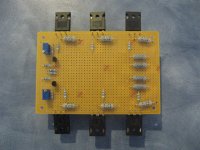
High Bias Current (4A) Version
Here is my high bias current version (4 Amps) of the F5 using 3 output pairs.
It is also the first time I have done a point to point circuit using perf board (I hope all goes well).
I still need to solder the output mosfets.
Well I hope this encourages others to try out this amp.
I should have this up and running by the end of the week.
Attachments
Wow! 4 amps! How much power do you expect the amp can produce?
Looking forward to seeing your finished amp.
Wachara C.
Looking forward to seeing your finished amp.
Wachara C.
Total power is still the same.
However max "class A" power is increased espescially into lower impedance loads (eg 4 Ohms).
Harmonic Distortion is also improved.
However max "class A" power is increased espescially into lower impedance loads (eg 4 Ohms).
Harmonic Distortion is also improved.
I've got a question about R21/R22.
Mr PASS says that the value could be from 10K to 22K.
Is there something to modify if using 15K ?
What is affected by those resistors values ?
I'm using FQA12P20 and FQA19N20C MosFets, provided by EUVL (thanks to him).
Thanks for your help
Mr PASS says that the value could be from 10K to 22K.
Is there something to modify if using 15K ?
What is affected by those resistors values ?
I'm using FQA12P20 and FQA19N20C MosFets, provided by EUVL (thanks to him).
Thanks for your help
Total power is still the same.
However max "class A" power is increased espescially into lower impedance loads (eg 4 Ohms).
Harmonic Distortion is also improved.
Does paralleling output devises also effect the damping? And if so, how do you calculate the damping?
Damping factor is inversely proportional to output impedance.
Since their is no resistor at the output which would dominate the output impedance.
Then in theory damping factor should increase (ie output impedance reduce) proportionaly by parralleling output transistors (for this design), Eg if damping factor is 80 for 1 pair then damping factor should be 240 with three pairs.
Well that is how I see it.
Damping factor is usually quoted for an 8 Ohm load therefore DF=8/output impedance.
So for a damping factor of 80 the output impedance equals 0.1Ohms.
If you want to calculate the output impedance (not knowing what the damping factor is) then it is not that straight foward. Negative feedback comes into it.
I use LTspice to determine such things.
Thanh1973, I am a noobie and i have not yet learn to model on LTspice. Are you going to model the output impedance for your parallel output tranny F5? If so and it is not to much trouble, would you mind also working it out for 2 parallel output trannies.
I am asking because I am currently building an amp with 2 output pairs and 28v rails for 4 ohm speakers.
Thanks,
Nick
I am asking because I am currently building an amp with 2 output pairs and 28v rails for 4 ohm speakers.
Thanks,
Nick
Here is my high bias current version (4 Amps) of the F5 using 3 output pairs.
It is also the first time I have done a point to point circuit using perf board (I hope all goes well).
I still need to solder the output mosfets.
Well I hope this encourages others to try out this amp.
I should have this up and running by the end of the week.
So what are you using to heatsink this monster?!
Uriah
I have built a prototype test set up for the purposes of testing amplifiers. It consists of a flat piece of aluminium which is bent in the shape of a U. On one side is mounted one F5 channel and on the other side I have mounted a Swiftech CPU heatsink and fan (run off a 9V battery). I have a attached a thermocouple to the aluminium right next to one of the devices that will monitor temperature while testing. I also have another thermocouple that I can use to measure temperature difference between each device.
I hope to fire it up for the first time today. I am not sure I will get to 4 Amps using this test setup, but we will see. If all goes well I will repeat some of the test Nelson has done just to see how it performs.
I will also take some pictures.
I hope to fire it up for the first time today. I am not sure I will get to 4 Amps using this test setup, but we will see. If all goes well I will repeat some of the test Nelson has done just to see how it performs.
I will also take some pictures.
- Home
- Amplifiers
- Pass Labs
- F5 power amplifier