sangram said:
If it's not too much trouble, could you share that separately?
Im no tube expert
On that grounds I would build either Aikido or maybe look at Diy Hifi Supply
But you better ask at Tube forum about this
Aikido +2
Aikiko +2 John Broskie's circuit is a perfect match for an F5 power amp from both a "temperment" and gain standpoint. (BTW, the gain can be tailored from unity to 50 via selection of the input and cathode-follower tubes.) Check out John Broskie's new "All-In-One" board with integrated B+ and heater regulated power supplies which he recently began shipping.
Aikiko +2 John Broskie's circuit is a perfect match for an F5 power amp from both a "temperment" and gain standpoint. (BTW, the gain can be tailored from unity to 50 via selection of the input and cathode-follower tubes.) Check out John Broskie's new "All-In-One" board with integrated B+ and heater regulated power supplies which he recently began shipping.
Re: Aikido +2
Are you sure about unity gain
dcbingaman said:
Aikiko
the gain can be tailored from unity to 50 via selection of the input and cathode-follower tubes.
Are you sure about unity gain
Re: Re: Aikido +2
When using a 6as7 triode the MU is around ~2. That's pretty darn close to unity gain.
Broskie's tube chart
Ron
tinitus said:
Are you sure about unity gain
When using a 6as7 triode the MU is around ~2. That's pretty darn close to unity gain.
Broskie's tube chart
Ron
Parallel layout
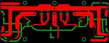
Hello, I made some adjustments based on earlier comments to my layout for a F5 with parallel output mosfets. Can anyone take another look through for potential issues?
Also 2 questions,
1. Is it better to route the signal traces around the perimeter of the board v. crossing under the power and output trace?
2. Will the thermal compensation circuit still work with parallel devices, and if yes do I need a thermistor at each mosfet or just one per p/n channel?
Thanks everyone for entertaining a noobies questions and of course NP for everything you share.
Attachments
Re: Parallel layout
I usually put all my power and output tracks at one end of the PCB away from small signal tracks.
npapp said:Hello, I made some adjustments based on earlier comments to my layout for a F5 with parallel output mosfets. Can anyone take another look through for potential issues?
Also 2 questions,
1. Is it better to route the signal traces around the perimeter of the board v. crossing under the power and output trace?
2. Will the thermal compensation circuit still work with parallel devices, and if yes do I need a thermistor at each mosfet or just one per p/n channel?
Thanks everyone for entertaining a noobies questions and of course NP for everything you share.
I usually put all my power and output tracks at one end of the PCB away from small signal tracks.
Re: Parallel layout
The Oracle sees all, tells all.
1 It doesn't matter as much as you think it does.
2 Yes, and No.

npapp said:1. Is it better to route the signal traces around the perimeter of the board v. crossing under the power and output trace?
2. Will the thermal compensation circuit still work with parallel devices, and if yes do I need a thermistor at each mosfet?
The Oracle sees all, tells all.
1 It doesn't matter as much as you think it does.
2 Yes, and No.
Re: Re: Parallel layout
Answers from the master chef himself. Thank you
Now I just need to find sinks to dissipate 160w per channel
Nelson Pass said:
The Oracle sees all, tells all.
1 It doesn't matter as much as you think it does.
2 Yes, and No.
Answers from the master chef himself. Thank you
Now I just need to find sinks to dissipate 160w per channel
Re: Re: Re: Parallel layout
I'm the Oracle, not a miracle worker.

npapp said:Now I just need to find sinks to dissipate 160w per channel
I'm the Oracle, not a miracle worker.
Re: Re: Re: Re: Parallel layout
Papa oracle, do you see me happy with an F5 in the near future?
Nelson Pass said:
I'm the Oracle, not a miracle worker.
Papa oracle, do you see me happy with an F5 in the near future?
Heat sink
npapp,
You can get huge heat sinks in Switzerland.
They offer from 20mm up to 1000mm length.
I do not know much about the seller, but this PDF looks interesting:
www.elinter.ch/media/img/01 Homepag...ofil kuehlkoerper/Datasheet-EL-M-P215-77A.pdf
Perhaps you need two of them in full lenght?
Sure very expensive to USA, but who knows...
Power Supply
Dear Oracle,
Does really no one like to explain how those thermistors should be calculated?
Post #4604
I'm confused, because you used two of them in your circuit from Power Supply First Watt F3 :
www.firstwatt.com/downloads/F3-service-manual-sm.pdf
Thanks for sharing.
I'm pretty sure you are not interested in this, but i miss something:
My Edit Button. Can i get some?
That would be enchanting.
Regards Sisyphism
Re: Re: Re: Re: Parallel layout
good sense of humor
Nelson Pass said:
I'm the Oracle, not a miracle worker.
good sense of humor
Sisyphism,
According to the PDF file one cl60 works for a 300va/230v transformer.
The CL60 imeasures 10 ohms@25° and 0,5 ohm@2.5Amp
One for each transformer will work fine.
The one to ground is usefull too.
You cannot make a mistake if you follow the PDF.
Your prior schematic was right to my sense.
http://www.gesensing.com/products/resources/datasheets/cl.pdf
Post #4638 one CL60 works for 110/120Vac 300VA transformer. For 220/240Vac use try two CL60 in series.
Is not the PDF showing the opposite?
-one cl60 for 220v
-two cl60 for 110 v
I use one per 250va 220v transformer.
I never have blown any 1.25T fuse.
Parts selection - F5 Monos
Hi all,
i gathered 90% of the parts for my F5 Monos only some of the Panasonic 3w resistors and the thermistors are missing but before i order the missing stuff from digikey i have some questions left, maybe you can help me out.
1. What digikey part number to choose for the 4.7k thermistors? They have like a gazillion different types avaible and i am getting confused here.
2. The power supply: I want to go full mono with one 330VA transformer per channel and C-R-C-R-C, but i still have problems choosing the right values for R, C will be 22.000uF 50V Nichicons.
So, in the original stereo f5 we have C-R-C, 30.000uF - 0.1175R - 30.000uF
Thats for stereo, my amps are mono so there will be only have the current flowing, so I can double the resistance to 0.22R and will still have the same voltage drop, since i want to go C-R-C-R-C i need to split up the resistance equal and end up with 22.000uF - 0.11R (2x0.22R 3W) - 22.000uF -(2x0.22R 3W) - 22.000uF per rail. Should give the same Voltage drop as the original supply and since 12W rating for the resistors is ok for a stereo amp i guess i should be on the safe side using 6W for my monos, , or did i oversee something fundamental?
Thanks for your help
- Home
- Amplifiers
- Pass Labs
- F5 power amplifier