Hi,
watch the ripple on the first cap if you adopt a rCRC supply.
If you increase the loading or increase the 0r1 between the caps the ripple on the first cap will quite soon exceed the ripple capacity of that cap.
You can avoid this ripple vs ripple capacity by using many cheap lower uF caps in parallel for that first cap. 3300//3300//3300//3300uF has four times the ripple capacity of a 3300uF cap and probably has more than a single 22mF as well. 4700uF and/or 2200uF would work just as well, find what is cheapest and available and fits the space.
massimo said:While I don't know the other brands, the Pana TSHA are quite famous as nice sounding caps with a good quality/price ratio.
I'll go for those!
Ditto. If Pana's are good enough for Papa they're good enough for me too.
My (still to be finished) mini Aleph amp uses TS-HA caps in the PSU.
For the F5 I'm thinking of using 4x 33000µF 35V Panasonics TS-UP (DK part # P6924-ND) instead of 8x 15000µF. Any thoughts on my choice?
AndrewT said:Hi,
watch the ripple on the first cap if you adopt a rCRC supply.
If you increase the loading or increase the 0r1 between the caps the ripple on the first cap will quite soon exceed the ripple capacity of that cap.
You can avoid this ripple vs ripple capacity by using many cheap lower uF caps in parallel for that first cap. 3300//3300//3300//3300uF has four times the ripple capacity of a 3300uF cap and probably has more than a single 22mF as well. 4700uF and/or 2200uF would work just as well, find what is cheapest and available and fits the space.
Max ripple for a single TSHA 22mF/35V is 5 A @ 120 Hz (according to the datasheet).
I'm using a 250VA 0-19 0-19V xfrm for each channel.
I think it should be OK.
The 0.1 ohm (5 x 0.47 ohm/3 W) will be adjusted to get a proper voltage according to the xfrm regulation %, thus it can be a little higher.
A power thermistor will be added in series with the primary with no bypass, as Nelson does.
Beftus said:
Ditto. If Pana's are good enough for Papa they're good enough for me too.

Even if I think Nelson is using 85° Panas and not 105°
download PSUD11 and check properly.massimo said:I think it should be OK.
Renron said:

I found the datasheets and the ripple curent for all of them if fairly close...~5 Amps rms.
Not really sure what that means...
In consideration of the life time of the capacitor, the operating ripple current should be lower than the 5A (rms) rated at 120Hz.
When F5 is under pure class A operation, the maximum class A current is 2.6A. This value is deemed as peak-to-peak ripple current to the filter capacitor. So, the peak current is 2.6/2= 1.3A (peak). Meanwhile, the ripple current shape is sawtooth so that rms value is 1.3/square root(3) = 0.75A(rms), which is much less than 5A (rms).
Even if F5 is under operation with max. continuous 10A, it is estimated as 2.9A(rms) following the same way above, which is still less than 5A (rms).
")
Thank you Nicoh and Babo
If I consider that Nelson is using for the first cap a pair of Pana TSUP 15mF/25V (4.63 A x 2 = <10 A) for both channels and I would like to use a 5 A rated cap for a single channel, I cannot undestand why I should be wrong.
Andrew: my problem with PSUD are xfrm parameter and diode type, not listed. A sym can be only approximate.
pro said:PI isn't a bit overkill is it?
I have made an experiment with 2 x 47000uf only, no resistor ( no pi filter), one channel supplied.
Result:
No hum with 93db efficiency speakers.
Though i have made no measurements.
Ok for me i will go this way
HOT DIGGIS 
Seems like I asked the right questions this time!
AndrewT, Babowana, Massimo, You guys are Awesome!
Class is in Session!!!
Wonderful explainations, formulas and debates.
I'll probably go with the Pannosonics.
Thank you all,
As far PSUDII goes it workd great for tube PS but does not have the functions required (like a Thermsistor soft start) for this large, power hungry Class A amp.
Ron
hi all
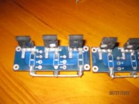
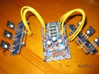
heres the pics of the output boards i want to add to the f5 for more power
i realise i will have to change the devices mounted to the baords
and already have enough of the f5 output devices to do this
the f5 will be run the same as the aleph 5 in the pics with 3x n and 3x p devices per amp mounted to the boards via flying leads
when i do this can i crank up the voltage and bias to get more power seeing as im running 6x output devices instead of 2
what sort of power can i expect into 4 ohm and what are ther plus and minus of this approach
regards sheafer
Attachments
slr 5000 said:hi all
what sort of power can i expect into 4 ohm and what are ther plus and minus of this approach
regards sheafer
B+ * (b+/ speaker impedance)
If using higher B+ then beware of power dissipation into output transistors and heatsink.
I usually use belt and braces and have a large heatsink plus a couple of fans, one sucking at one corner and the otehr blowing out at the opposite corner.
when i do this can i crank up the voltage
And what about the input JFets?
conversion to 3pair output stage
Hi,
the maximum output power depends totally on the PSU voltage that is available when delivering that maximum power.
The maximum ClassA current depends totally on the bias current you set for the output stage.
The three FETs located near each other will defeat most attempts to dissipate the extra heat expected if you increase the bias by a factor of three and will be exacerbated if you also increase the PSU voltage.
slr 5000 said:i have some if i need to add more
in parralell
do i need to ?
The input jfets would not appreciate to see more than 24v rails.You'll need to cascode them . Here is an example. (input stage only)
(Buzquito JM Plantefève)
Attachments
- Home
- Amplifiers
- Pass Labs
- F5 power amplifier