Re: Heatsink touch-test
I use one 200x120x45mm heatsink for each transistor. I can touch the heatsink 4-5 second now with 23ºC and 80% humidity. In summer the mid temperature is 31ºC and 58% H, so i think the most intelligent is to use other type of amplifiers in summer, like gainclones, class d or AB... The F5 amplifier design ignores the Kyoto Protocol and energy saving.


steveleen said:I have completed one F5 channel - standard circuit/parts, with point-to-point wiring on breadboards (no pcb).
After successful adjustment to specified voltages, after one hour warm-up, the heatsink touch-test is giving me 2-3 seconds bearable touch duration at the edge of the heatsink and I really can't go past 4 seconds. This seems just within spec to me. Note the following:
- I am using one aluminum heatsink (unpainted) per device
- ambient temperature is around 26-28 degrees C and relative humidity ranges from 70% to 90% (I'm in Jakarta, not far from the equator).
No need to reply to this post unless someone has warnings or concerns regarding the temperature.
Thanks,
Steve
I use one 200x120x45mm heatsink for each transistor. I can touch the heatsink 4-5 second now with 23ºC and 80% humidity. In summer the mid temperature is 31ºC and 58% H, so i think the most intelligent is to use other type of amplifiers in summer, like gainclones, class d or AB... The F5 amplifier design ignores the Kyoto Protocol and energy saving.
hum
This is how my amp started life. It explains why I had trouble.
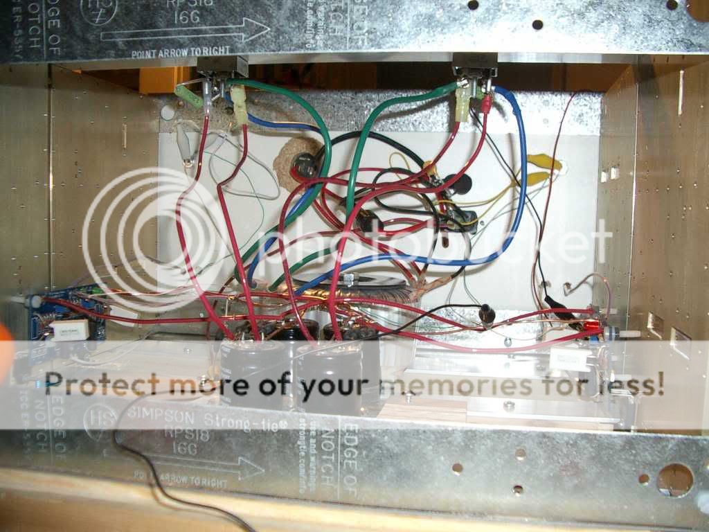
Here I've shielded the transformer but I still had my signal ground going to the power star ground. Later I twisted it together with the signal wire and added a drain shield at the RCA end. This eliminated the noise until I plugged in an unshielded interconnect and the noise came back so I had to add a shield to that too.
Stein2,
You didn't have problems because you were smart and properly braided your wires.")
Also, I have a wood panel between my transformer and interconnects.
-Garrett
stein2 said:
Interesting... This is how I built both my dual-mono F5s, no hum, no interference, no problems....
This is how my amp started life. It explains why I had trouble.
Nelson Pass
Assuming that the amp is not actually miswired, then it's almost
always the magnetic field radiated by the transformer. You can
rotate or move the transformer, and of course any distance you can
place between signal wiring and transformer will help.
Very often the transformer field creates a ground loop issue between
the input grounds being connected together at the source. You can
check for this by using a pair of shorting plugs on the inputs or by
lifting the input ground on one channel.
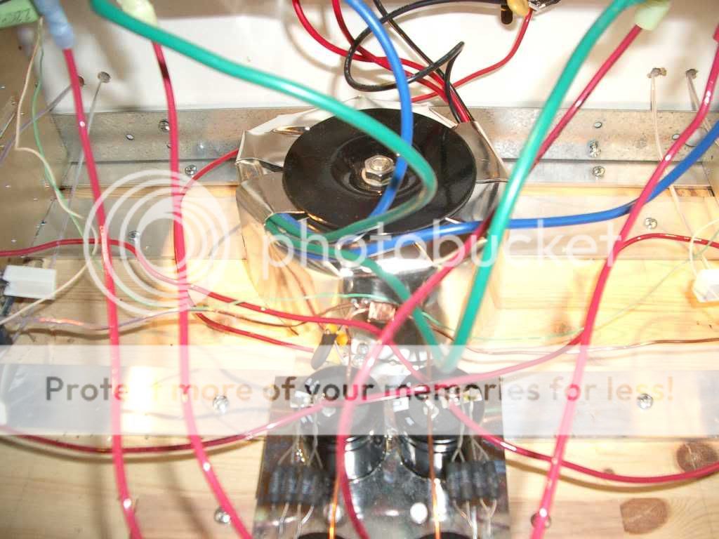
Here I've shielded the transformer but I still had my signal ground going to the power star ground. Later I twisted it together with the signal wire and added a drain shield at the RCA end. This eliminated the noise until I plugged in an unshielded interconnect and the noise came back so I had to add a shield to that too.
Stein2,
You didn't have problems because you were smart and properly braided your wires.
Also, I have a wood panel between my transformer and interconnects.
-Garrett
juluska said:31ºC and 58% H
The beauty of forced cooling with a fan is the option of selecting between silent low-rev operation and full air flow speed on hot days by the flick of a switch.
Natural convection seems a painfull choice for regions with sustained +30C temperature levels.
I live in an area that's very quiet most of the time, only during weekend day hours in the summer season there's noise from tourist walkabouts/drive-by's, once a year occasions are classic Rolls/Bentley/Ferrari club parades drive passing my front gate mail box.
With all double-glazing windows and doors closed it's like living in a vacuum, a heavy transport truck passing by at 50 feet from the front door can be felt but not heard.
Occured a number of times a few years ago when a few additional houses were built in my street, but about as common as a truck driving through a cemetery.
With all windows closed and on a good ear day, i really need to do my best to hear the fans of my last forced cooling amp project in the low revolution setting.
The amps produce 260W of heat per channel, dropping the heatsink temperature by +10C's with a couple of clip-on fans for the hot summer months would be easy on a Pussy F5.

This is my problem, I don't have the proper type of thermometer. The closest thing around is that my wife has an oven thermometer - the type that sits up like a little alarm clock, but it seems to sense ambient temperature only.
Could we make a guess at the mosfet temp by taking a voltage reading from the thermistor? - along with a measure of the distance from the thermistor to the device?
Thanks, Steve
Could we make a guess at the mosfet temp by taking a voltage reading from the thermistor? - along with a measure of the distance from the thermistor to the device?
Thanks, Steve
steveleen said:Could we make a guess at the mosfet temp by taking a voltage reading from the thermistor? - along with a measure of the distance from the thermistor to the device?
Thanks, Steve
Thermistor is certainly good enough for this job -- depending upon the type there should be a chart of resistance vs temperature on the manufacturer website. Barring this you can also calibrate the resistance vs temperature by measuring it at room temperature, then measuring it in boiling water (at sea level)...here's an application note from ILX on calibrating a thermistor:
http://www.ilxlightwave.com/appnotes/AN 4 REV02 Thermistor Calibration and Steinhart Hart.pdf
I've found that a digital cooking thermometer works almost as well as the thermal probe for my Tektronix DM502A.
Once you cal the thermistor, you can also determine the thermal impedance of your heat sink...
Re: hum
Well, one image, thousand words...
alazira said:
This is how my amp started life. It explains why I had trouble.
...
Stein2,
You didn't have problems because you were smart and properly braided your wires.
Also, I have a wood panel between my transformer and interconnects.
-Garrett
Well, one image, thousand words...
thanh1973 said:It seems this is a very revealing amplifier.
Can anyone suggest cd/sacd that would be a good match for it.
Don't spit on me for this, but even with the Philips CD630 my system now sounds like it cost a million bucks...
Bob Dylan has been long staying with me . . .
From "A Hard Rain's A-gonna Fall"
Not through flying-fighters . . .
"Together Through Life" flowing through B1/F5,
melting into my mind . . . Hmm . . .
Nice music . . .
Long live, Zimmerman . . .
And, more please . . .
From "A Hard Rain's A-gonna Fall"
Not through flying-fighters . . .
"Together Through Life" flowing through B1/F5,
melting into my mind . . . Hmm . . .
Nice music . . .
Long live, Zimmerman . . .
And, more please . . .
Attachments

Suitable CD Player
If I buy a new cd player I am thinking of buying a SACD player. My choice is between spending as little as possible on something that has potential for modding or just spending a couple of grand and get something decent out of the box.
So I have narrowed it down to:
Sony SCD-CE595 SACD/CD Changer - cheap but good
Marantz SA-11S2 - I am really not sure I can afford this but it is ready to go out of the box.
If I buy second hand then it could be something like:
Arcam Alpha that can be modded.
or other (eg Philips CD630)
It doesn't surprise me that you like the Philips CD630. I checked out the specs, it looks like it has the TDA1541 DA converter in it which quite a few peope like.
If anyone can give me a few more suggestions that would be appreciated.
I have Marantz SA-14 SACD/CD player, quite expensive.
But, I don't have any SACD . . .
The life of the pick-up was very short.
I had to buy a new pick-up, heck . . . sky expensive.
I have also a cheap CD player as a transport . . .
And, a cheap DAC, class-A descrete output . . .
Now I use these. Total price was much cheaper
than Marantz SA-14.
Nevertheless, Sonic quality puts Marantz aside . . .
Hope you will choose good value . . .
What about this: http://us.hifidiy.net/Article.asp?articleid=207
Has anyone bought one of these?
What do you think?
I am also potentially interested in buying or building a hard drive player.
Has anyone bought one of these?
What do you think?
I am also potentially interested in buying or building a hard drive player.

Ok, Thanks and Sorry to everyone.
I didn't want to start a new thread, because my question specifically relates to the the F5 amp.
A few people have not been entirely happy with the sound of their F5. So rather than mess around with the amp I thought it made more sense to look at the source.
I didn't want to start a new thread, because my question specifically relates to the the F5 amp.
A few people have not been entirely happy with the sound of their F5. So rather than mess around with the amp I thought it made more sense to look at the source.
tinitus said:Sure
On firstwatt site about F5 I believe it says that what comes in comes out, sort of
It may sound like its exstremely sensible to any changes
Why not make a dedicated thread about how people do it, I mean about complete setup
Setup is very easy --- probably easier than any amp you want to build. Even just getting the bias correct yields a good (great) sounding amp with remarkably low THD.
If you want to get more complicated, the source resistors on the JFETs and (according to NP) the 0.47 resistors can be tweaked to just about null out any distortion. But you need a good distortion analyzer, a very good signal generator, and a spectrum analyzer (or good sound card analyzer) to look at the distortion artifacts.
I've twiddled with other components and looked at the results -- probably out of some obsessiveness --but as I've said, out of the box this is a wonderful amp. If you just get the bias correct you're going to have a killer amplifier.
Adding Fans to F5
Thanks for the previous posts on measuring heatsink and device temperatures.
I have decided to add fans to my F5 to just slightly reduce the heat levels. I have two Papst 3414 NGL fans (EC, 24vdc, 1.5W), one for each channel. I want to keep this simple: no heat-sensing auto-on/off circuits; no separate power supply for the fans. I want to be able to turn them on or off using a switch on the back of the amp case.
I have constructed the F5 power supply exactly as specified in Nelson’s F5 user manual. My first tests used the 24v + and – rails directly and the fans ran too fast and loud. Inserting a 680 ohm resistor in series slows things down nicely and they are very quiet. When the amp is turned on, the fans twitch a bit, then start turning. The heatsink touch test after one hour gives me a good 5 to 10 seconds.
My concern is how to best wire the fans to the power supply for lowest electrical interference into the F5 signal stages. So far I am thinking:
- attach the fans negative leads directly to star ground
- tap into the DC on the power supply board, directly off the V+ and V- that the F5 circuits are using, or should I tap into the supply further back, or even directly off of the diode packages?
- attaching small caps across the fan leads (47uF – 220uF), or do I really need these given the filtering on the power supply itself?
- ensuring that the fan wires are separated from any signal wires
Any advice would be appreciated.
Steve
- Home
- Amplifiers
- Pass Labs
- F5 power amplifier