Re: hum
I found out the hard way that this amp is sensitive to picking up emf/rf noise if you have your speaker outputs or power cord close to your input rca's. I spent a lot of time on trying to fix my grounds but it wasn't a ground loop hum (sort of sounded like one but higher pitched and more staticky). I used magnet shield from lessemf.com around my transformer and this cut my noise in half. Using heavily shielded interconnects and adding a shield wire for the signal path internally eliminated all noise.
juluska said:I have this 100hz hum from psu. I use 8 x 10000uf caps. I suppose i must use more than 8 x 15.000 uf. What about 8 x 220000 uf, can these reduce this noise.
I found out the hard way that this amp is sensitive to picking up emf/rf noise if you have your speaker outputs or power cord close to your input rca's. I spent a lot of time on trying to fix my grounds but it wasn't a ground loop hum (sort of sounded like one but higher pitched and more staticky). I used magnet shield from lessemf.com around my transformer and this cut my noise in half. Using heavily shielded interconnects and adding a shield wire for the signal path internally eliminated all noise.
Re: Re: hum
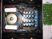
Interesting... This is how I built both my dual-mono F5s, no hum, no interference, no problems....
alazira said:
I found out the hard way that this amp is sensitive to picking up emf/rf noise if you have your speaker outputs or power cord close to your input rca's.
Interesting... This is how I built both my dual-mono F5s, no hum, no interference, no problems....
Attachments
Hi Floyd 42,
Diy audio is about the best thing there is. Like cooking,
we can adjust the flavor to suit our taste. I'm not really
an expert but it's my curiousity that led me to try many
things. Another trick that I've discovered is if your amp
soundstage is too forward, you can push it behind the
the speakers by using just 1 carbon resistor at the input
of the circuit or sometimes at the feedback loop but the
resistor must be the Brown color type like the brand AB.
Strange ya ?
JC951t said:
Strange ya ?
Not at all.
Good info from lively experience.
Keep going . . . !
")
Re: Load Needed for Adjustment?
Sorry about the ambiguity. I test with loads as a matter of course
since I also wish to look at distortion and such when adjusting.
If all you have is a voltmeter, then a load will not add anything to
the test procedure.
steveleen said:In the first two sentences of the second paragraph of the section on Initial Adjustment he states in an oddly phrased sentence that "Each channel does not need to be attached to a load in order to adjust it." But then he says that if the only load you have is a loudspeaker, he advises against using it - the implication being that some load is needed.
Sorry about the ambiguity. I test with loads as a matter of course
since I also wish to look at distortion and such when adjusting.
If all you have is a voltmeter, then a load will not add anything to
the test procedure.
Re: hum
Assuming that the amp is not actually miswired, then it's almost
always the magnetic field radiated by the transformer. You can
rotate or move the transformer, and of course any distance you can
place between signal wiring and transformer will help.
Very often the transformer field creates a ground loop issue between
the input grounds being connected together at the source. You can
check for this by using a pair of shorting plugs on the inputs or by
lifting the input ground on one channel.
juluska said:I have this 100hz hum from psu. I use 8 x 10000uf caps. I suppose i must use more than 8 x 15.000 uf. What about 8 x 220000 uf, can these reduce this noise.
Assuming that the amp is not actually miswired, then it's almost
always the magnetic field radiated by the transformer. You can
rotate or move the transformer, and of course any distance you can
place between signal wiring and transformer will help.
Very often the transformer field creates a ground loop issue between
the input grounds being connected together at the source. You can
check for this by using a pair of shorting plugs on the inputs or by
lifting the input ground on one channel.
Floyd42Flake said:Master-Hifi: The best music in the world is not very often preserved in the best recordings (for me e.g. The Beatles). We love this music and do everything to make it more enjoyable: Adding 2nd harmonics distortion to reconstruct real harmonics missing in the music (good luck!), warming up the sound (or give it more kick) using certain parts, varying the circuitry, using suitable concepts and so on... The resulting gear is in the best case breathtaking, seductive and loveable. (Yes, I have tube-amps in mind!
The ear wants what the ear wants.
Hi Nelson
I am not sure if you missed my post about the quasi-complementary output stage or if it is difficult to do, but anyway I have raised the stakes.
The first person that can produce a working quasi-complimentary output stage for this circuit gets a free packet of Tim Tams.
Just in case you guys don't know what Tim Tams are, they are the best tasting biscuits/cookies in the world that you can buy from the supermarket.
Edit: Made in Australia of course
thanh1973 said:Hi Nelson
I am not sure if you missed my post about the quasi-complementary output stage or if it is difficult to do, but anyway I have raised the stakes.
The first person that can produce a working quasi-complimentary output stage for this circuit gets a free packet of Tim Tams.
Just in case you guys don't know what Tim Tams are, they are the best tasting biscuits/cookies in the world that you can buy from the supermarket.
Edit: Made in Australia of course
look for Papa's Mosfet Citation pdf ( somewhere on Passdiy or Passlabs )
everything you need is there
Thanks for the info Zen Mod.
I'll have a look at this and see if I can do it myself.
The offer still applies though. Tim Tams for the first person who comes up with a working version of the F5 with quasi-complimentary output stage.
So now it is also competition to see if anyone can beat me to it.
EDIT: I can't access the pass site. It must be down temporarily
thanh1973 said:Thanks for the info Zen Mod.
I'll have a look at this and see if I can do it myself.
The offer still applies though. Tim Tams for the first person who comes up with a working version of the F5 with quasi-complimentary output stage.
So now it is also competition to see if anyone can beat me to it.
l' art pou l' art ?
why you want this ?
to spoil it's elegancy ?
replicate tube SRPP , ad Jfet input , and you're there
or White Cascode ..... or anything with tube

edit :
I think that you can disregard my Citation idea ...... I just mixed things .... threads .... whatever I mixed .........

Well I have never heard a quasi-comp design I didn't like the sound of.
So I was curious how this might change the sound of this amp.
I am not suggesting the F5 does'nt sound any good.
Not at all, I would just like to try different things and see what the effect might be.
I suppose I have a gut feeling I would very much like the end result.
I am fairly new to this hobby (therefore lack a lot of the technical ability to do this myself) I am also married with a baby, so time is extremely limited.
I should have studied physics at university and not materials science, and I should have started this hobby when I was young and single.
Oh Well, better late than never.
Heatsink touch-test
I have completed one F5 channel - standard circuit/parts, with point-to-point wiring on breadboards (no pcb).
After successful adjustment to specified voltages, after one hour warm-up, the heatsink touch-test is giving me 2-3 seconds bearable touch duration at the edge of the heatsink and I really can't go past 4 seconds. This seems just within spec to me. Note the following:
- I am using one aluminum heatsink (unpainted) per device
- ambient temperature is around 26-28 degrees C and relative humidity ranges from 70% to 90% (I'm in Jakarta, not far from the equator).
No need to reply to this post unless someone has warnings or concerns regarding the temperature.
Thanks,
Steve
- Home
- Amplifiers
- Pass Labs
- F5 power amplifier