Thank you @seventenths! It's toner transfer. I still have a few sheets of inkjet photo paper stashed away and replaced that laser printer 10 years ago but it never made it to the recycling as I can't seem to let it go in case I ever do another pcb ...
16 years later ... it doesn't get as much play time as it used to but it's still part of the lineup. The heatsinks are on the small size but I found that even at 1.0A bias, the harmonic profile of the F5 doesn't change (ratio of H2/H3 ...), it probably just doesn't stay in class A as long but at least it's avoided being retired.
I rebuilt it a few years ago into this case and updated the PSU but bumped it down to 1.0A to keep the heat under control.


I rebuilt it a few years ago into this case and updated the PSU but bumped it down to 1.0A to keep the heat under control.

I've had perfectly usable results in the past with little effort but a couple of recent trials have been sub-standard. . I'm tempted to try actual iron-on-transfer paper but will make another effort or two first, including the Archival Print function (higher temp) but that may be a step in the wrong direction. No harm in trying.Thank you @seventenths! It's toner transfer. I still have a few sheets of inkjet photo paper stashed away and replaced that laser printer 10 years ago but it never made it to the recycling as I can't seem to let it go in case I ever do another pcb ...
Cheers
Hello,That diy-etched F5 looks very familiar to me and brings back some good memories. If it's this one, with the addition of P3, I can testify that the layout works.
I took a short break because I got sick.
I will probably recover by the weekend.
Thank you very much to everyone who helped during this time.
I liked it a long time ago from this forum. I printed it on A4 paper using toner transfer and ironing method. Then I have to thank you for this beautiful pcb.
note: p3 is already mounted on the card.
Hi guys!
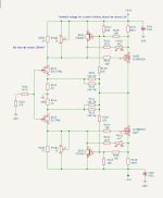
I hope you can give me a sanity check

It's an F5, for headphones (planars like Susvara, so gain is pretty much the same) with ALFET lateral MOSFETs from the givaway.
I adjusted some things:
1. Lowered bias resistors R105/106 and trimmers to 1k to be more in the range of ALFETs cutoff voltage. They start between 0,5V - 1,5V I gave some headroom, this should give me a nice play around 2,5V
2. Lowered the current protection to trigger around 2,6A. Still way too much, might go even further by lowering the R115/116 to 1Ohm to be around 1,3A. Still kinda much though.
3. I want bias around 150mA giving me a clean 1W @ 64Ohms with a huge margin. And MOSFETs like to be run hot.
My questions are as follows:
1. Is this a right direction?
2. Did I forgot about something and it will blow up in my face?
3. How to handle gain switch? Relay connecting additional resistance across R109/110/111/112, thus lowering the gain?
Thanks!
I hope you can give me a sanity check
It's an F5, for headphones (planars like Susvara, so gain is pretty much the same) with ALFET lateral MOSFETs from the givaway.
I adjusted some things:
1. Lowered bias resistors R105/106 and trimmers to 1k to be more in the range of ALFETs cutoff voltage. They start between 0,5V - 1,5V I gave some headroom, this should give me a nice play around 2,5V
2. Lowered the current protection to trigger around 2,6A. Still way too much, might go even further by lowering the R115/116 to 1Ohm to be around 1,3A. Still kinda much though.
3. I want bias around 150mA giving me a clean 1W @ 64Ohms with a huge margin. And MOSFETs like to be run hot.
My questions are as follows:
1. Is this a right direction?
2. Did I forgot about something and it will blow up in my face?
3. How to handle gain switch? Relay connecting additional resistance across R109/110/111/112, thus lowering the gain?
Thanks!
Attachments
- Home
- Amplifiers
- Pass Labs
- F5 power amplifier