Re: MOSFET Junction Temperatures
") I shudder to even imagine how you would know this!!
I shudder to even imagine how you would know this!!
****************************
Anyway, my mosfets are running at 1.3A each. Temp taken from the metal tab on the mosfet is only about 65degC or so (mica spacers on 12"x6"x2" heatsink well spaced apart. I'm thinking about pushing it a little higher!! Heatsink temp is in the high 40's.
One way I tried to deal with the temp in the case is to mount the heatsinks on the sides of the case, but mounted on 5mm spacers... ie the heatsinks "float" off the sides of the case by 5mm. The mosfets are attached to the heatsinks but the rest of the circuit is mounted on the inside of the case. Hard to describe without a pic - I'll try to take one tonight. Anyway, the point is that there is a separation between the interior of the case and the heatsink. The result is a cooler case - mid 30's or so.
*****************************
BTW to update on the mica spacers from mouser - the bigger ones listed back on the previous page, keystone 4661 (mouser 534-4661) work perfectly. The hole is a little near the top of the spacer but it does cover all the bottom of the mosfet. A winner so and cheap at 6c each.
Fran
dcbingaman said:. (Mine like to "mark" everything that is new, but we won't even go there - urine is VERY electrically conductive - I know from personal experience.)
I shudder to even imagine how you would know this!!****************************
Anyway, my mosfets are running at 1.3A each. Temp taken from the metal tab on the mosfet is only about 65degC or so (mica spacers on 12"x6"x2" heatsink well spaced apart. I'm thinking about pushing it a little higher!! Heatsink temp is in the high 40's.
One way I tried to deal with the temp in the case is to mount the heatsinks on the sides of the case, but mounted on 5mm spacers... ie the heatsinks "float" off the sides of the case by 5mm. The mosfets are attached to the heatsinks but the rest of the circuit is mounted on the inside of the case. Hard to describe without a pic - I'll try to take one tonight. Anyway, the point is that there is a separation between the interior of the case and the heatsink. The result is a cooler case - mid 30's or so.
*****************************
BTW to update on the mica spacers from mouser - the bigger ones listed back on the previous page, keystone 4661 (mouser 534-4661) work perfectly. The hole is a little near the top of the spacer but it does cover all the bottom of the mosfet. A winner so and cheap at 6c each.
Fran
Found an article that talks specifically about horizontal vs vertical heatsinks and it is VERY informative. Definitely vertical mounting is better, however by a small margin as we saw in Jackinnj's nomograph showed us. I think its a very good article for those of us who, like me, had no idea and assumed that horizontal was better.
http://www.google.com/url?sa=U&star...lKS0Cw&usg=AFQjCNFCp0KrgztMO7Dcl-BSHY7ZeUW18Q
It seems that best sink placement is vertical and if, for instance, your sink is 150mmx150mm then you want the fins to be 7.5mm apart from each other to provide best convection between the fins and that the taller the fins are, after a point, the worse the convection gets, as Pooge suggested. In this example best fin height was 1" or 25mm. Check it out. Its a good, short, informative paper.
Uriah
I think the two papers are very different and actually dont even speak on the same subjects. One is about placement of the heatsink as its title suggests : Comparing naturally cooled horizontal baseplate heat sinks with vertical baseplate heat sinks and the next talks about OPTIMUM DESIGN AND SELECTION OF HEAT SINKS
A read of both will lead the reader to select an aluminum extrusion or aluminum bonded fin sink with appropriate fin length, height, spacing and then to mount it vertically with the fins in a vertical orientation and to make that selection because we DIYers dont normally like the sound of a fan buzzing along on our active heatsink.
Uriah
Vertically elongated fins are a given.
The word "vertical" has been too loosely batted around here, often not referring to the same thing. The terms "length"', "width", and "height" are also used inconsistantly in many sources, especially when referring to the fin dimensions.
The paper I sited is to support the issue that started this back in posts 2828-2831 regarding tall heat sinks vs. short and wide as normally encountered. Both have vertically elongated fins and back plates. However, one is more volumetrically and weight efficient from a thermally equivalent stand point. Tall sinks are at a disadvantage from this stand point. They can work from a thermal point of view, but cost and weigh more for the same dissipation. But they may offer an advantage of layout, floor space, and looks, if that is your preference. I happen to value these features for monoblocks, but I may have to pay for it.
Re: supply
sekess -
I was out of town yesterday, and then this heatsink melee broke out, so sorry if my response is three pages down the road.
If the Avel is putting out 18v under load, your rectified DC should be in the area of (18 x 1.4) or 25.2 volts, minus two diode drops of .6v each, so 24v. Any resistance in the supply will cause a further drop of I (current) times R (resistance). When you're talking multiple amps of current draw, even a small resistance can cause a drop of one to two volts.
By the way, your new arrangement will have a net R of (.47/4) which is close to .12 ohms, fairly close to half of your original .2 R, so you will drop a slight bit less in terms of your final voltage. But you know what? It's no biggie. The amp will actually work over a much larger voltage range than what we're talking about here. Build and enjoy. - Pat
sekess said:Each channel's supply has 120,000uF of capacitance and I used .2 ohms for the CRC resistors.
On this supply, the resistance will be a little less - I was planning on using 4 parallel .47ohm resistors (like Nelson uses in his amps) instead of the .2 ohm that I used the last time. But, I think the small difference will be insignificant with respect to the rail voltages.
sekess -
I was out of town yesterday, and then this heatsink melee broke out, so sorry if my response is three pages down the road.
If the Avel is putting out 18v under load, your rectified DC should be in the area of (18 x 1.4) or 25.2 volts, minus two diode drops of .6v each, so 24v. Any resistance in the supply will cause a further drop of I (current) times R (resistance). When you're talking multiple amps of current draw, even a small resistance can cause a drop of one to two volts.
By the way, your new arrangement will have a net R of (.47/4) which is close to .12 ohms, fairly close to half of your original .2 R, so you will drop a slight bit less in terms of your final voltage. But you know what? It's no biggie. The amp will actually work over a much larger voltage range than what we're talking about here. Build and enjoy. - Pat
supply
Thanks Pat and Peter,
So, using the same calculation with 20v secondaries would give me 26.8v before the resistor drop and any other losses. And as you indicated, the 18v secondaries would give 24v before resistor drop and losses.
So, any advantage to going with the 20v secondaries and a slightly higher rail? Or, will either one yield the same performance.
Yes, that was a pretty intense heatsink discussion -- interesting though.
Thanks,
Steve
Peter Daniel said:It worked with 5V rails last time I was checking
Excellent! That means I can connect all kinds of stuff backwards, and it will likely still work.
Re: supply
Steve -
I'd just stick with 18v, since it's the "official" standard Pass power supply configuration, and Nelson, as you have discovered, is kind enough to design all of his new creations around that configuration. One power supply - many amplifiers.
If you want to invest another $50 or so in a permanent power supply solution, you might consider swapping out the resistors for a pair of Hammond 159 inductors. 10 amp capacity, 2.5mh, .044 ohms DCR. They'll get you as close to the design center of 24v DC as you're likely to get with any resistive element in the supply. Just orient them for least hum - keep them away from the audio circuitry to the extent that you're able. - Pat
sekess said:
So, any advantage to going with the 20v secondaries and a slightly higher rail? Or, will either one yield the same performance.
Steve -
I'd just stick with 18v, since it's the "official" standard Pass power supply configuration, and Nelson, as you have discovered, is kind enough to design all of his new creations around that configuration. One power supply - many amplifiers.
If you want to invest another $50 or so in a permanent power supply solution, you might consider swapping out the resistors for a pair of Hammond 159 inductors. 10 amp capacity, 2.5mh, .044 ohms DCR. They'll get you as close to the design center of 24v DC as you're likely to get with any resistive element in the supply. Just orient them for least hum - keep them away from the audio circuitry to the extent that you're able. - Pat
CPU cooler
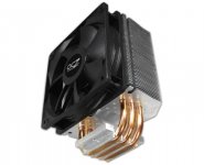
What about putting CPU coolers (fan-less or with regulated fans) - one per each transistor. Like the one attached. Such coolers with whisper quiet fans (or without) have thermal resistance around 0.15 C/W. That is effectively 100W at 40 DEG C max with room temp. 25 DEG C.
These beasts are much more effective then conventional "audiophile" heat sinks and much cheaper. Available in ANY local computer shop.
Attachments
Re: CPU cooler
What happens of a fan fails? You know that grinding sound when the bearings in those cheapo fans get loaded with dust. The amplifier goes up in smoke?
What we need is a lesson in making copper heat pipe heat sinks with Freon inside. The ones that look like a Miami Beach high rise condo building.
coh-b-pyky said:What about putting CPU coolers (fan-less or with regulated fans) - one per each transistor. Like the one attached. Such coolers with whisper quiet fans (or without) have thermal resistance around 0.15 C/W. That is effectively 100W at 40 DEG C max with room temp. 25 DEG C.
These beasts are much more effective then conventional "audiophile" heat sinks and much cheaper. Available in ANY local computer shop.
What happens of a fan fails? You know that grinding sound when the bearings in those cheapo fans get loaded with dust. The amplifier goes up in smoke?
What we need is a lesson in making copper heat pipe heat sinks with Freon inside. The ones that look like a Miami Beach high rise condo building.
Re: Re: CPU cooler
I agree that fans are not reliable. I believe there are designs floating around for a temperature controlled cut-off switch. Would these be a prudent back up plan?labjr said:
What happens of a fan fails? You know that grinding sound when the bearings in those cheapo fans get loaded with dust. The amplifier goes up in smoke?
......
Conductivity of Urine
Suffice to say it wasn't my idea.....when I was a wee lad I relieved myself on the wrong barred wire fence....I only noticed the insulators after the fact.
BTW, I received (8) 22000 mfd / 35V power supply caps from Digikey today - they are smaller than C-cell batteries !! As I get older, it's like EVERYTHING is getting smaller......
Originally posted by dcbingaman
As I get older, it's like EVERYTHING is getting smaller
But this may be a consequence of your youthful encounter with the electric fence?
Aengus said:
But this may be a consequence of your youthful encounter with the electric fence?


- Home
- Amplifiers
- Pass Labs
- F5 power amplifier