I did some listening test on channel that works.
I can say I prefer the Mepco capacitors over the Mallory.
The sound became too smooth (not bad but somehow, something missing) and the dynamics (attack) also became a bit less.
It became a bit too smooth to my taste (!) of course this capacitors are first time in an amplifier (NOS) VS the Mepco I used those over the years for testing. I think I will mix the Mallory with the Mepco, (I have 4PC from both of them) that is my next plan, that way will have two very same PS. Before the PCB I will put the pair Mepco.
Maybe it just need to be break in? I don't know.
One more time not bad but something missing how I heard the amp previously.
Maybe the Zen Mod idea about the Philips poly-carbonate (yellow) caps not always useful?
Ha, ha, ha -, I am kidding Zen.
I'm always serious
Except when I'm always joking

https://www.diyaudio.com/community/threads/ludef.369990/post-6997306
Except when I'm always joking
https://www.diyaudio.com/community/threads/ludef.369990/post-6997306
Again, Eh, Not that simple
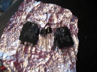
I replaced all the semi conductors, (pull of two miniature eyelet at the J Fets, Fix it under a magnifying glass)
measured all the resistors accept the two 5W type.
I mounted into the smaller test model set it up all DMM and no bias at all.
Again the same issue.
I pull it a part and now to found out one of the Fukushima R 0.22 5W resistor is open without any burned mark.
I will replace that soon let see, fingers cross.
It is a very simple, little amp giving me so much trouble!
Attachments
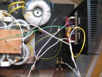
PROBLEM solved, now I have bias, I set it up 900mA at 19V rail voltage. I will let it warm up an our or so, so the bias it settle down.
At least electrically working, latter some listening tests.
Very likely all the removed semis are all good and this 5W resistor was the problem from the start.
At least electrically working, latter some listening tests.
Very likely all the removed semis are all good and this 5W resistor was the problem from the start.
This amplifier runs hot!!
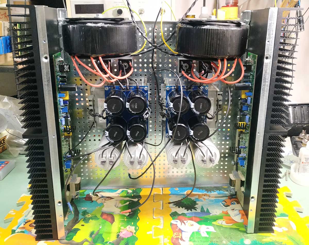
Set up both channel in the bigger enclosure (it supposed to be twice as big heatsinks for this amp).
Total bias between the PCB+ and rail V+ measured 1.1 Amp after 1 hour warm up, without music. Across the 5W 0.22R I measure 236 mV.
Unfortunately I do not have 18V transformer, I got 20-0-20V and that gives me extra 4VDC total 28VDC rail voltage under load under load.
I measured the temperature around the mosfets 50 Celsius without music.
For now I leave it like that, the second channel needs a pot for the signal and ready to use.
I think I will build this amp based on the F5m in the right enclosure like 5Kg heat-sink / channel.
I have 2 matched pair of the bigger Toshiba mosfets and with those. I love the sound so why not.
I also think about the F4 version but I am not sure if that can be driven with most of the pre-amplifiers?
Zen you know that, please let me know. Thank you!
Greetings
Hello,
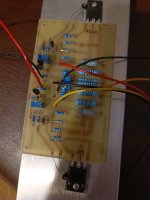
I finished making it a long time ago but it was waiting due to jfet pairing.
I measured 0.65v on R11 and R12, but even if I reduce it to 0.4v on p1 and p2, they are still very hot. Right now I gave 19v for testing. I'm afraid it would burn if I used it for 24v testing.
I measured 0.6v from the speaker output at idle
Sorry for my english Thank you for your help.
I finished making it a long time ago but it was waiting due to jfet pairing.
I measured 0.65v on R11 and R12, but even if I reduce it to 0.4v on p1 and p2, they are still very hot. Right now I gave 19v for testing. I'm afraid it would burn if I used it for 24v testing.
I measured 0.6v from the speaker output at idle
Sorry for my english
Thank you for your help.Short the inputs to your F5 and adjust P1/P2 so that the dc output (ie. the dc offset) is as close to zero as you can. Doesn't matter if the voltages across R11 and R12 aren't quite equal. The important thing is for an bias current level, you always want the DC offset to be close to zero. Anything less than 50mV in magnitude is acceptable, though the lower the better.
What voltages do you see across the resistors R5/R6/R7/R8?
What voltages do you see across the resistors R5/R6/R7/R8?
Hello again,
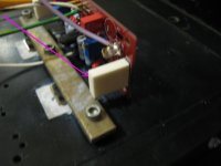
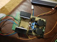
I reset p1 and p2 by turning them counterclockwise. I tried to adjust p1 and p2 by watching R11 and R12 and I saw that my voltage fell below 18 volts. I stopped the adjustment. I decided to install another 25v power circuit for healthy adjustment.
It showed R11 0.25v and R12 0.20v. I was going to continue adjusting where I left off. At that moment, a smell spread in the room, I immediately pulled the power plug, it smells like a burnt resistor, but nothing can be seen in the image for now.
I need to do detailed research
Attachments
If voltage drop across R11 and R12 are low (low output mosfet current) and yet the power supply voltage sagged, the current must have taken a different route, perhaps through the input jfets.
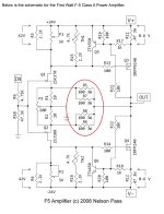
You mentioned that you had doubled the jfets, and the amplifier board does not look like the diyAudio pcb. So the jfet circuit needs to be checked and the pcb needs to be checked to be sure that it conforms to the schematic. The schematic for the modified jfet circuit needs to be checked too.
As for the power supply current draw, the voltage across R5/R7, R6/R8 that Dennis asked for and also the voltage across R1 and R2 would tell if too much current is going through the jfet circuit.
- Home
- Amplifiers
- Pass Labs
- F5 power amplifier