In the past, I have published the odd schematics of projects that I have built, plus the odd photos. So this is going to be the first publication from me for a project from start to finish.
A few disclaimers first :
a) All the information I have to offer is as published.
b) You can copy, modify, DIY, commercialised, ... as you want.
I have no illusion of any intellectual property rights by publishing on the Internet.
c) I cannot offer any components (PCBs, matched FETs, ...) or finished products.
You have to do it yourself.
d) This is not a project for beginners.
You need to be able to etch double sided PCBs to finer than 0.5mm.
You should be able to drill to 0.5mm diameter.
And you need to be able to match SMD FETs in SOT-23.
Now the story.
Like many, I started audio DIY using opamps (ICs) but have gone discrete over the years. A few years back, I read the article by Nelson Pass on discrete opamps, and thought how nice it would be if one can make something similar in a compatible size. Back then, there were few choices of SMD JFETs or bipolar transistors for that matter, not to speak of matched duals. So nice idea, but I did not need it bad enough to follow on.
There are literally hundreds of websites on the internet for discrete opamps, including finished products, schematics, photos, ...., etc. I have attached a few links for well known circuits here (FETs). There are equally many circuits based on bipolar transistors, e.g. from Jensen & D. Self. You just need to google :
http://www.borbelyaudio.com/pics/305borbely-new.pdf
http://www.passdiy.com/pdf/diyopamp.pdf
http://www.forsselltech.com/downloads/schematics/Class A JFet Opamp.PDF
http://www.diyaudio.com/forums/showthread.php?s=&threadid=61888&highlight=
Although they are claimed to be sonically better than their IC counter parts, and with finished modules selling around US$40 per opamp for DIY upgrades, I have yet to see a discrete opamp design which is size compatible to a standard DIP-8 package, like e.g. a NE5534.
Well, so what !! Except that you try to use them on a PCB that will fit nothing but a standard DIP-8.
Around Christmas 2007, I was looking through the website of Linear Systems and realised that they could offer LSK389s in SOT-23-6 packages. It re-ignited my thoughts on a discrete opamp in DIP-8 size, and a quick layout followed which would have fitted a 10x10mm footprint.Well, would have. Of course the LSK389 is only available in SOT-23-6 in theory.
The attached document describes my approach to doing just that - a discrete all-FET opamp in DIP-8 package.
Enjoy.
Patrick
Attachments
A few additional remarks perhaps.
The circuit is pretty standard, as published by Nelson & others. The changes made were more out of necessity than desire, though I think the BF862 in this case is arguably a better part. The only "disadvantage" is the high bias. But then the high bias allows you pure Class A output (Class B not possible anyhow) of +/- 15mA.
If your application does not support the 40mA it consumes, you can either use BF861 instead (they come in 3 grades of Idss), or with slight changes to the PCB use LSK170s.
Soldering is tricky because of the tight space, but not more difficult than any other SMDs. Matching SOT-23s is a very interesting experience. Do put a current limiter of say 30mA on your power supply. Once setup, it took me an hour to measure 100 devices.
The most difficult is the layout. It looks simple now, but it was a week's work and 7 versions before it gets to this state. As you can see, there isn't really much room left for more complicated circuits like current mirrors or folded cascodes, ...., etc. There is, however, room on the PCB for a ceramic compensation cap in 0603 (e.g. Murata). There is no small silver mica SMDs I can find on the internet. So I myself would solder it external.
The DC offset is thermally sensitive. You need to trim DC offset using the actual supply voltage. Once it stablises, especially with the heatsink, it remains very stable. I could get DC stable to within 2mV over time on a close loop gain of 11.
The compensation cap also depends on the close loop gain. The higher the gain, the smaller the cap, as expected. I found that I need to use 220p for a gain of 5. Again, recommend testing in a dummy setup close to the actual application. I have no problems finding small enough silver micas to allow direct soldering onto the 2 adjacent pins (Pin 6 & 8). Similarly, additional trimming resistors can be soldered externally between Pins 7 & 8.
You can make 10 of these for less than 100 Euros, buying parts from RS and making your own PCB. Heatsinks cost about 1 Euro each from Buerklin, as are the 0.8mm pins (20 cents each). Not bad at all considering you have to pay similar or more for an OPA627, LME49710, or even AD797. The price will drop by a factor of 4 if you order 1000 FETs from Digikey. But that I suppose is something only for group buys.
")
Patrick
The circuit is pretty standard, as published by Nelson & others. The changes made were more out of necessity than desire, though I think the BF862 in this case is arguably a better part. The only "disadvantage" is the high bias. But then the high bias allows you pure Class A output (Class B not possible anyhow) of +/- 15mA.
If your application does not support the 40mA it consumes, you can either use BF861 instead (they come in 3 grades of Idss), or with slight changes to the PCB use LSK170s.
Soldering is tricky because of the tight space, but not more difficult than any other SMDs. Matching SOT-23s is a very interesting experience. Do put a current limiter of say 30mA on your power supply. Once setup, it took me an hour to measure 100 devices.
The most difficult is the layout. It looks simple now, but it was a week's work and 7 versions before it gets to this state. As you can see, there isn't really much room left for more complicated circuits like current mirrors or folded cascodes, ...., etc. There is, however, room on the PCB for a ceramic compensation cap in 0603 (e.g. Murata). There is no small silver mica SMDs I can find on the internet. So I myself would solder it external.
The DC offset is thermally sensitive. You need to trim DC offset using the actual supply voltage. Once it stablises, especially with the heatsink, it remains very stable. I could get DC stable to within 2mV over time on a close loop gain of 11.
The compensation cap also depends on the close loop gain. The higher the gain, the smaller the cap, as expected. I found that I need to use 220p for a gain of 5. Again, recommend testing in a dummy setup close to the actual application. I have no problems finding small enough silver micas to allow direct soldering onto the 2 adjacent pins (Pin 6 & 8). Similarly, additional trimming resistors can be soldered externally between Pins 7 & 8.
You can make 10 of these for less than 100 Euros, buying parts from RS and making your own PCB. Heatsinks cost about 1 Euro each from Buerklin, as are the 0.8mm pins (20 cents each). Not bad at all considering you have to pay similar or more for an OPA627, LME49710, or even AD797. The price will drop by a factor of 4 if you order 1000 FETs from Digikey. But that I suppose is something only for group buys.
Patrick
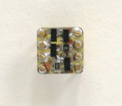
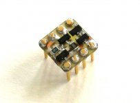
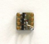
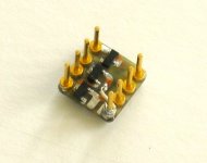
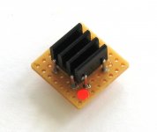
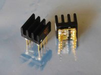
EUVL said:Aren't they cute !!
(Not yet potted, or else you will see nothing much .... )
Patrick
They are cute, indeed
- Status
- This old topic is closed. If you want to reopen this topic, contact a moderator using the "Report Post" button.
- Home
- Amplifiers
- Pass Labs
- Pass Discrete Opamp in DIP-8 Package