VCXO Reclocker
The Tentlabs VCXO turned up in the mail today, so I had a chance to attempt to get the D1 reclocking circuit running and installed.
After fixing a couple of minor errors and installing a missing jumper from VCXO output to 4020 - meaning the loop was missing from PLL - and the D1V3 started making music again.
Currently the VCXO is running without PLL biasing, and VCXO is sharing a regulator with the other PLL ic's so there is definitely room for improving performance.
Even at this stage, my initial impressions are that it's well worth going to the effort to reclock. I still need to A/B the vcxo to be certain of the extent of the changes but there seems to be quite a bit more fine detail being resolved. The sound stage has developed a sense of depth that was lacking previously.
Re: VCXO Reclocker
Lacking? Really?
I think you mean that the depth of the sound stage has been improved.
spzzzzkt said:Even at this stage, my initial impressions are that it's well worth going to the effort to reclock. I still need to A/B the vcxo to be certain of the extent of the changes but there seems to be quite a bit more fine detail being resolved. The sound stage has developed a sense of depth that was lacking previously.
Lacking? Really?
I think you mean that the depth of the sound stage has been improved.
housing...
yes I mean comparative. I don't know what kind of music you listen to, but I had on Miles Davis's B*tches Brew last night. It's fantastic music but mastering on the version I have isn't that spectacular. On the track B*tches Brew I had for the first time a real sense of the cavernous space that producer Teo Macero had created. Sure, previously there was a sense of the performers being widely spaced in a clean wide soundstage, but the VCXO has stepped that up to a much more defined sense of ambience. My speakers and room are really a limiting factor in my system at present but the improvement in depth was quite clear.
Based on what I've heard I think there was a good reason the original D1 used secondary PLL reclocking, and i believe without it you are getting perhaps 75-80% of the performance the D1 circuit is capable of.
cheers
Paul
Had a chance to A/B the VCXO/recovered clock for the first time today. I've wired in the PLL and I'm sure it's not currently optimal. Nonetheless there are very distinct differences between the two.
Method was to swap the jump between settings without touching volume control or powering off anything. This means a couple of seconds of audible digital hash but nothing too nasty.
After repeated swaps, playing the first 4-5 minutes of Fire Waltz from Eric Dolphy at the Five Spot Vol.1 it pretty clear there is a substantial difference between the two. The following comments are comparative between the two versions and the D1V3 is still very impressive in stock form.
Using the recovered clock the picture presented is warm and lush. There is a sense of things being slightly impressionistic, individual musicians are slightly indistinct and perhaps "smudged". The sound staging and depth is quite good but to my ear it's slightly difficult to pin point the instrument precisely. It's still a very attractive presentation and I suspect this could be the musicality Spencer is aiming for.
With the vcxo providing the clock things change quite dramatically. It's not as immediately attractive, as the some of the lushness and warmth seem to have been stripped away. But then you realise that the instruments occupy very precise positions in the sound stage, and easier hear the detail in each instrument. The nuances of Dolphy's playing for example are clearly audible.
I might have to revise my "exaggerate for effect" 20-25% downwards slightly, but I stand by my comments that there is a very significant improvement to be gained from implementing the vcxo.
cheers
Paul
Pass D1 without Enhancements
For a bit of perverse fun I've decided to layout a PCB for a fairly "straight" D1 with on board secondary PLL/VCXO and unmodified MOSFET I/V. I've also decided to follow the original 78**/79** based power supply just for kicks.
This is not a reflection on the quality Spencer's board. I rather not hack the D1V3 board up to try out these "de-tweaks" and I would really like to hear what the "unenhanced" design sounds like
cheers
Paul
With all the potentially junk pcm63's in circulation I doubt there is much real point in making another version of a PCM63 based D1, so I put that on the back burner til I think about how I want to proceed.
Looks like the clock baord is back on the agenda.
My vcxo got some more attention today. The previous setup was non ideal, with 2 regulators on the board. One reg supplied VCXO and IC's the other supplied the PLL bias. I decided to bypass the PLL bias for the moment and dedicate one reg to the VCXO and the other to the ic's.
This has improved the sound significantly. Before the changes I was starting to feel the sound was a little too thin. Giving the VCXO it's own reg seems to have improved the situation.
A separate PSU for the clock board probably needs to be next addition as voltage rail I'm using seems to sag (from 5V to 4.6V) under the load.
Prompted by the discussion of fake PCM63's I've made an attempt to analyse the output of the D1V3 by recording the output into a digital recorder and then checking the files on computer. Obviously this introduces a whole lot of variables including the ADC chip in the recorder and impedance matching etc so it's not really accurate.
What I did find was that the noise floor in the right channel was significantly higher than the left. This was cured by wrapping the ac supply lines to the digital section in adhesive copper tape and covering with heat shrink. I'm still seeing a spike at 50hz and spikes at 100hz and multiples there of extending out to 22khz. I'll change out the kimber kable wiring to the output jacks for shielded mic cable and see if this helps. The other possibility is that this rectifier related noise could be originating from eBay-ed OSCONs I installed in the transport PSU recently.
Another minor issue had been that attempting to set "point B" on right negative to zero volts was non-linear and extremely twitchy. After checking the current and voltages at various points in the JFET I/V against figures supplied by Spencer the problem was narrowed down to a faulty 5K trimpot. Replacing the trimpot resulted in same zeroing behavior as for the 3 other I/V sections.
The replacement PCM63P-Y arrived from A'af so the D1V3 is now fully Y equipped, tho' I am none-the-wiser as to what that actually means!! The D1V3 sounds really quite nice in this configuration.
cheers
Paul
Housing,
thanks for kind words.
I haven't had a chance to check the result of replacing the iffy oscons in the T1 with 2200uf/50V Panasonic. There was no obvious signs of improvement when I check the rails on the scope before and after the cap change over. OSCON were probably OK but you have to check these things.
This throws the suspicion back on the way I have the D1V3 set up. The DAC regs are powered from the +/-12V Digital supply. This might be one area I need to address, as it means there is one stage of regulation on the DAC supplies. The PASS D1 used three stages of regulation for the DAC analog supplies and two stages for the digital. The 12V supply for the digital is really a bit low to implement a second stage of regulation as the lm3x7 and 78/79 regs need a drop of at least 5V to perform to spec.
I'll experiment with powering the DAC analog stages from the 18V jfet I/V supplies and see if that improves the situation at all.
cheers
Paul
I've rewired the DAC supplies so they feed from the regulated 18V I/V supplies and I think this makes an improvement in terms of detail.
I'm still getting psu noise on the right channel. The only thing I can think might be causing this is that there is a 10R or 12R resistor in the PSU CRC for the right analog supply. The original was toasted when I installed the Dead-on-arrival PCM63P-Y, and I replaced with the nearest value I had on hand. This would mean perhaps 2-3mv extra ripple according to Duncan's PSU simulator. Perhaps this is enough to make the difference??
I'd been having issues with the test tone cd I'd made. I was getting noise spikes 20dB down from the -70dB test tone. I remade the test track with MBIT+ dithering and this really cleaned up the DAC output. Obviously the spikes were related to quantization noise.
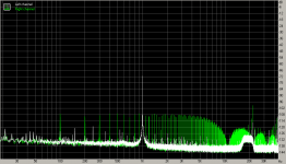
PSU noise is currently about -106dB down in the right channel. Left is significantly better and I'm hoping to get the noise in the right down to similar levels. Obviously the PSU noise isn't audible at this level but I'd much prefer to have both channels clean down to the noise floor.
note: the "bump" in the noise floor near 20khz is the part of MBIT+ dither. I'm recording the DAC output into a Tascam HDP2 running at 24bit/88khz sampling rate then analyzing the file using RMAA 6.0.4.
I'm still getting psu noise on the right channel. The only thing I can think might be causing this is that there is a 10R or 12R resistor in the PSU CRC for the right analog supply. The original was toasted when I installed the Dead-on-arrival PCM63P-Y, and I replaced with the nearest value I had on hand. This would mean perhaps 2-3mv extra ripple according to Duncan's PSU simulator. Perhaps this is enough to make the difference??
I'd been having issues with the test tone cd I'd made. I was getting noise spikes 20dB down from the -70dB test tone. I remade the test track with MBIT+ dithering and this really cleaned up the DAC output. Obviously the spikes were related to quantization noise.
PSU noise is currently about -106dB down in the right channel. Left is significantly better and I'm hoping to get the noise in the right down to similar levels. Obviously the PSU noise isn't audible at this level but I'd much prefer to have both channels clean down to the noise floor.
note: the "bump" in the noise floor near 20khz is the part of MBIT+ dither. I'm recording the DAC output into a Tascam HDP2 running at 24bit/88khz sampling rate then analyzing the file using RMAA 6.0.4.
Attachments
Scratch the rambling about the CRC resistor above. After thinking about it this is on the negative supply and would effect both channels equally.
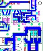
Looking a the pdf of the board layout, I noticed that the digital supply rectifiers are really quite close (under 10mm) to supply decoupling caps for one of the right channel DACs. This seems to be something that needs to be investigated more closely as some kind of shielding could be required.
I've also noticed that the -12V supply is now unused since rewiring DAC regs to 18V supplies. Looking at the board layout it seems like minor surgery is required to reconfigure as a +12V supply. This is ideally located to be used as a dedicated clock supply.
Attachments
I've tried applying copper tape to C177 (see attachment to previous post) and the top of the adjacent DAC and this seems to have substantially reduced the rectifier noise on the right channel. I'm not sure if this is a problem with the diodes Spencer supplies but if you are using TO220 schottky's I'd highly recommend applying some kind of shielding. It's probably worth doing anyway given the proximity of the DAC to the rectifiers.
ha!!
tracked down the rectifier noise to a cordless phone near to where I was placing the recorder I was using to capture the D1V3 output. Power off the phone base station - noise pretty much disappears from the recording.
Shielding on the cap and dac chip were probably unnecessary.
tracked down the rectifier noise to a cordless phone near to where I was placing the recorder I was using to capture the D1V3 output. Power off the phone base station - noise pretty much disappears from the recording.
Shielding on the cap and dac chip were probably unnecessary.
Not sure if there is a PMD100 "issue" as such. I haven't got mine running properly but that could be construction error. I just get nasty distorted sound. The SM5842APT I'm using sounds pretty good so I have spent much effort debugging.
Don't populate the XO section - it apparently doesn't work correctly according to Spencer's reports. You simply jumper J9 "CLK Sel" between the center pin and 8412 position - this connects MCLK to XTI.
Don't populate the XO section - it apparently doesn't work correctly according to Spencer's reports. You simply jumper J9 "CLK Sel" between the center pin and 8412 position - this connects MCLK to XTI.
I just ordered the kit from Spencer, it seems like a real value when compared to Digikey prices.
I picked the 9001 + PMD100 combo. I wouldn't know how to hook up a VXO so I figured I better go for the reciever with the best PLL.
I went with the PMD100 because I am addicted to its sound in my old Audio Alchemy DAC, I really have never heard another filter like the PMD100. So I am hoping I can get it to work with this board.
I've decided to revive my efforts to do a fairly straight D1 layout. I'm pretty keen to see what can be achieved using the original power supply, mosfet I/V, and Lithium Tantalate VCXO. I've managed to get my hands on one of the fujitsu LT VCXO, but I also think I may have found a current production smd replacement from a german manufacturer. I'm waiting for a response to a query about obtaining small quantities.
While reading Guido Tent's supply decoupling document I came across an interesting observation regarding the internal layout of the analog and digital sections of the PCM63. By rotating the 90 chips degrees from the layout used in the D1V3 it's possible to cleanly separate the digital and analog sections of the board. Initial attempts at laying out the dac chips in this configuration look pretty nice, and the analog and digital supplies seem like they will work out quite well. Don't hold your breath, but I'll post something more when I've got something substantial to share on my version of a D[iy]1.
While reading Guido Tent's supply decoupling document I came across an interesting observation regarding the internal layout of the analog and digital sections of the PCM63. By rotating the 90 chips degrees from the layout used in the D1V3 it's possible to cleanly separate the digital and analog sections of the board. Initial attempts at laying out the dac chips in this configuration look pretty nice, and the analog and digital supplies seem like they will work out quite well. Don't hold your breath, but I'll post something more when I've got something substantial to share on my version of a D[iy]1.
- Status
- This old topic is closed. If you want to reopen this topic, contact a moderator using the "Report Post" button.
- Home
- Amplifiers
- Pass Labs
- Pass D1V3 DAC - build thread