I found some IRF610 in my stuff and I'm about to start a BOSOZ project.
The only thing bugging me off is, how "special" does the power supply have to be?
looking at this...
http://web.vip.hr/pcb-design.vip/bls-pwr.html
...
cant i just give it +/- 60v dc and be happy")
the problem is the IRF9610 in that psu, I cant find it localy and I dont want to order it via internet for this project, the closest I can get is the IRF9630, any good?
The only thing bugging me off is, how "special" does the power supply have to be?
looking at this...
http://web.vip.hr/pcb-design.vip/bls-pwr.html
...
cant i just give it +/- 60v dc and be happy
the problem is the IRF9610 in that psu, I cant find it localy and I dont want to order it via internet for this project, the closest I can get is the IRF9630, any good?
i did a stupid thing today. i powered up my BOSOZ power supply
without loading the V+ with 15 Kohms ¼ watt to ground and the
V- with 15 Kohms... i blew all the zeners and the mosfets.
just when you think you're learning something...
POOF, you let the magic smoke out...
well, i guess i at least learned not to do that.
could someone explain to me why it does this without a load?
thanks
m.
moe29 said:i did a stupid thing today. i powered up my BOSOZ power supply
without loading the V+ with 15 Kohms ¼ watt to ground and the
V- with 15 Kohms... i blew all the zeners and the mosfets.
just when you think you're learning something...
POOF, you let the magic smoke out...
well, i guess i at least learned not to do that.
could someone explain to me why it does this without a load?
thanks
m.
It's been so long since I built mine I can't remember that happening to me. I couldn't tell you why. Where in Florida are you located? I am in Lakeland close to Orlando.
i'm in Clearwater
i just de-sodered all the zeners (all toast) and the MOSFETS.
i guess the caps are still good, not sure about the diode bridges.
my RS voltmeter has a diode setting. when i check the bridges,
it gives me a reading, but it's not stable... the V just keeps
increasing...
i did double check all the parts values, cap polarity, zener polarity,
etc. I mean it's not that difficult to stuff a board with the correct
parts... i suppose the parts blew because i didn't add the resistor
loads before turning on the power supply...
m.
moe29 said:i did a stupid thing today. i powered up my BOSOZ power supply
without loading the V+ with 15 Kohms ¼ watt to ground and the
V- with 15 Kohms... i blew all the zeners and the mosfets.
just when you think you're learning something...
POOF, you let the magic smoke out...
well, i guess i at least learned not to do that.
could someone explain to me why it does this without a load?
I never heard of that. I do believe I checked the PS of my BLS with no load and nothing really happen. Sounds to me like you got bigger problems than the lack of a 15 kohms load.
I can't remember if I had mine hooked up to the circuit or not when I powered it up. I don't think the absence of a load would cause all that damage. Things to consider would be did it occur on both the + and - side. Without the mosfet or zeners installed power up and make sure you have + volts on the + side making sure that your bridges are in right and not backwards. I think if you hit those zeners backwards they will blow and I'm thinking of any way the voltage could wind up wrong. Everyone who has ever made a mistake with this stuff has looked right at it 20 times wondering why before it hit them. Be persistant, it will work. Sometimes I walk away and come back later. Good Luck
i just double checked the point to point wiring for the
transformers and all is well there, i'm getting 38 volts AC
on the secondaries. The transformers are Avel Lindberg
Y236107's rated at 2x115v - 30v secondaries. Am i
getting 38V becasue of the 115v trans?
i just checked the bridges and the polarity is correct.
it may have been that the zeners were no installed
correctly... i allready de-soldered them! and i didn't
take a picture to document.
i agree absence of a load shouldn't have caused that...
when i get new zeners i'll triple check for correct polarity.
thanks for the replys, i'll get back to you when i try again!
this always happens when i try to build things from scratch!
i've built lots of kits with no problems....
---------------------------------------------------------
I did as PassFan suggested and took some readings
without the zeners or MOSFETs installed. Reading
across the caps right after the bridges i was getting
+103.5 VDC and -104.4 VDC. i notice these readings
are a lot higher than the 80VDC reccomended from
the article... could this be because of no load?
m.
Hi Ilianh,
Sorry if I highjacked your thread with my problems...
i've read on here somewhere where someone said that
it didn't make to good of a headphone amp... something
about not enough gain?
here's a thread that talks about a "Zen" headphone amp,
and there's even a construction article if you read the whoe
thing - in there somewhere... lots of positive reaction!
http://www.diyaudio.com/forums/showthread.php?s=&threadid=2451&highlight=zen+headphone
Your voltage is wrong. It should not be that high, it should be at the 80 volts it is supposed to be at. When you load it down the current increases not the voltage. Double check that you have dual secondary windings and that they are wired in series. With dual windings of 38v each wired in series is 76 volts x 1.414 would be about what you are getting...crap. Don't power it back up on that until someone smarter than me gives more advice.
You can also do a search for this in the Pass forumn to see if someone else had a similar problem. The calculation works out so it's not wired wrong I just question this high a voltage. Normally with 30 volt windings in series you have 60v x 1.414 would give you around 80 volts. The zeners are set up on that voltage to tell the mosfet what level to regulate at. With your voltage being higher the circuit will not behave properly. With smaller trannies you have to take out zeners. With bigger ones I don't know
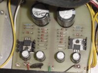
Don't give up as people will help you figure it out given time. Tommorrow evening I may be able to post a pic of my board on my power supply
You can also do a search for this in the Pass forumn to see if someone else had a similar problem. The calculation works out so it's not wired wrong I just question this high a voltage. Normally with 30 volt windings in series you have 60v x 1.414 would give you around 80 volts. The zeners are set up on that voltage to tell the mosfet what level to regulate at. With your voltage being higher the circuit will not behave properly. With smaller trannies you have to take out zeners. With bigger ones I don't know
Don't give up as people will help you figure it out given time. Tommorrow evening I may be able to post a pic of my board on my power supply
There is nothing wrong per se with having 104 volts, it's just due to a crappy transformer with 15% regulation. Just make sure your first caps after the rect. are rated hi enough. I used
a C-R-C-Reg sequence after the bridge to cut down on the dissipated power on the series mosfets where the first C was rated at 150VDC. R dropped about 25 volts to put me into a more reasonable voltage range.
Moe,
don't get too scared if the 750 resistors get hot. Hot they will get, VERY hot, about 130 deg C if my memory is correct, with the small sinks the mosfet will get toasty as well.
Initially I soldered the 750 ohm resistor 1/2 inch from the pcb to give a little more ventilation. I also put all the hot stuff on the top and all the caps on the bottom to keep them cool.
Ilianh said:You guys think this could be used as a headphone amp?
What headphones impedance would be safe?
Yeah, well let's say it's not eminently suited as a headphone amp because the gain drops drastically on outputs below 1k.I am using the highest gain version and have to turn the volume control almost all the way up.It also creates hell with the volume settings where the the attenuator doesn't seem to have any effect on volume in the middle range and the last clicks are huge increases.Otherwise the sound is pretty good.
- Status
- This old topic is closed. If you want to reopen this topic, contact a moderator using the "Report Post" button.
- Home
- Amplifiers
- Pass Labs
- BOSOZ Psu