Hi,
It surprised me if Mr. Pass used only one bridge (for 2 channels). One bridge for two channel means one transformer for two channels, or both channel share the same transformer.
Using dedicated power supply to each channel you will get better separation (you know what I mean).
May be you saw a monoblock, may be not. Mr. Pass is supposed to have built plenty of Alephs, so some of them may be with dedicated power supply, some with shared power supply.
Dedicated power supply may be not economical (if we talk about price to performance ratio). But Audiphiles always choose the non-economical way. As an audiophile and a businessman, I think Mr. Pass had managed to build both.
I've seen a single bridge going from positive to negative rail.
There's also 2 bridges, one from positive rail to ground, the other from ground to the negative rail. Are the peak currents lower in each bridge? Is the resulting ripple better or anything? There has to be some reason to go through the extra trouble.
That can be separate from whether there's a separate supply per channel.
As long as the circuit is right, I cannot see why there should be a problem with the wiring. I only have a little doubt on the capacitors.
I guest the transistors are double pined (diode) and the caps are in parallel with each diode, and the caps are at least 100n. I won't hear any different whether the caps are 100n, 10n, or null, but I will have a bad feeling using 100n. I'll prefer 10n.
I guest the transistors are double pined (diode) and the caps are in parallel with each diode, and the caps are at least 100n. I won't hear any different whether the caps are 100n, 10n, or null, but I will have a bad feeling using 100n. I'll prefer 10n.
Hi Jay
Do you have any experience with thes bridges ? That 10n value, did you calculate it or is it a commonly used value ?
I also downloaded that snubber/rectifier formula, but didn't get a proper calculation yet.
The value used on this bridge was chosen after reading about 'm on the net.
Grtz,
Nick
Do you have any experience with thes bridges ? That 10n value, did you calculate it or is it a commonly used value ?
I also downloaded that snubber/rectifier formula, but didn't get a proper calculation yet.
The value used on this bridge was chosen after reading about 'm on the net.
Grtz,
Nick
Sandy H. said:Sorry I can't answer your question, Electro-Nick, but could you point me to the link where this rectifier assembly is described by Peter? I am completely unsure of the capacitor application and wanted to learn a little more about it.
Thanks!
S.
The single caps is a simplification of the snubber which might help and it might not. The source used in this forum seem to be mostly:
http://131.109.59.51/images/pdf/Calculatin_ Optimum_Snubbers.pdf
Electro-Nick said:Hi,
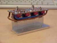
I made a bridge just like Peter.
Nick
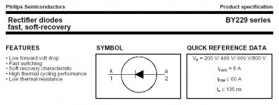
Would these diodes be good for such a bridge on an Aleph30?
BY229-400
Attachments
Electro-Nick said:Hi Jay
Do you have any experience with thes bridges ? That 10n value, did you calculate it or is it a commonly used value ?
I also downloaded that snubber/rectifier formula, but didn't get a proper calculation yet.
The value used on this bridge was chosen after reading about 'm on the net.
Grtz,
Nick
Hi Nick,
I don’t have any experiences with snubbers. But is that a snubber circuit you are building? I cannot see the resistor! The diode shown by Peter is of a faster type (TO-95?). You asked about the 10n. I think the snubber caps value is different from circuit to circuit.
Well, this is what Pete Godreau wrote in his article about this snubber:
“Since most everything else has been addressed, it seemed reasonable to see if anything could be done to improve the performance of this unit as well..”
If I get him right, I don’t have no reason why I should be bothered with such circuit. What I can see is that this is very microscopic. Something you should do with proper math and apparatus. Even a simple high/low pass filter, cannot easily be synchronized between calculation/theory and reality.
With rectifiers, I choose only the ones from good manufacturers (you can trust the product specs), slow or fast. For the noise (more importantly in CD player), adding EMI filter is a lot easier. Oh, I got several bridges, but I still cannot decide which one is the best, the fast ones or the slow ones. They are different, indeed.
Hello Jay,
The problem with the calculation is that i don't know the exact working voltage and current yet. First i have to build the amp together, then i can measure some things. The pcb with diodes has already space to try a range of caps. Maybe indeed the cap can be left out. Also there is no resistor in yet.
The used diodes (MBR type) may be silent enough to do the job. I'll just have to try and see")
It wouldn't be much fun if everything worked at once, then there would be no work left for us as DIY'ers
Grtz,
Nick
The problem with the calculation is that i don't know the exact working voltage and current yet. First i have to build the amp together, then i can measure some things. The pcb with diodes has already space to try a range of caps. Maybe indeed the cap can be left out. Also there is no resistor in yet.
The used diodes (MBR type) may be silent enough to do the job. I'll just have to try and see
It wouldn't be much fun if everything worked at once, then there would be no work left for us as DIY'ers
Grtz,
Nick
Electro-Nick said:It wouldn't be much fun if everything worked at once, then there would be no work left for us as DIY'ers
Grtz,
Nick
What a statement!
Unfortunately, DIY’er is not my primary occupation anymore. But still I waste my time (and money) on audio, just for fun. BTW, what is the amplifier going to be? It must be single ended, Zen or Aleph. Why not try the circuit with CD player first? If you report a huge improvement, I will copy your circuit and apply it to my CDP without modification.

Electro-Nick said:Look at my website, i've posted some pics there.
Goeie dag Nick
Some nice stuff you've build so far

What is the size and make of those caps and trafo of your A5?
Where is the pics of your finished BoSoZ ?
Groete
JDeV
- Status
- This old topic is closed. If you want to reopen this topic, contact a moderator using the "Report Post" button.
- Home
- Amplifiers
- Pass Labs
- Bridge rectifiers for Aleph