What you're describing is basically a hybrid amplifier. It's been done many times. Two things to watch out for:
--Unless you use a follower in the front end, the output impedance will be high. This will tend to roll off the top end when interacting with the Gate capacitance of the MOSFETs in the output.
--Run the tubes as hard as you dare. You'll need every milliamp you can get in order to drive the output stage decently.
Grey
John Broskie's Aikido would be a suitable tube preamp for Mosfet power followers. It's has a follower output stage and certainly has lower output impedance that a simple common cathode stage. The ECC83 would have an output impedance in the order of 1k, but obviously another tube in the follower stage might be better. Check the tubecad pages for details.
GRollins and MRupp
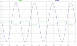
i am sorry for the late response. i was trying to simulate the circuit in LTSpice. i am not an expert in this field. bot some how i managed to simulate it. please check the attachment and advise me to improve the quality without loosing the simplicity.
i am sorry for the late response. i was trying to simulate the circuit in LTSpice. i am not an expert in this field. bot some how i managed to simulate it. please check the attachment and advise me to improve the quality without loosing the simplicity.
Attachments
renjiish, I like your idea  Actually, I've been thinking I would work on something similar after the projects I'm now working on
  It has been said by some that tubes do their best when voltage amplification is necessary. Their linearity and soft clipping characteristics where the music's dynamics and gain are involved are noticably better than semiconductor topologies.
I have a question or two though; why 12AX7 is in the sim schemo when you originally suggested ECC83? Just because your sim library only has the 12AX7??? I ask because my first choice would be a 76 (I have a few). Following some suggestions from Lynn Olson. Have you read http://www.nutshellhifi.com/triode1.html ?
Do you intend to give correct bias to the second stage via R2? It's losing 1/2 your signal voltage? Avoiding a coupling cap though
Have you thought of driving the cascoded power JFET rather than a MOSFET? Might be more do-able with only 2 stages?
I really hope this thread devlopes a little more. I'm not to experiecnced with Tubz but I'ld like to get into it soon
Actually, I've been thinking I would work on something similar after the projects I'm now working on It has been said by some that tubes do their best when voltage amplification is necessary. Their linearity and soft clipping characteristics where the music's dynamics and gain are involved are noticably better than semiconductor topologies.I have a question or two though; why 12AX7 is in the sim schemo when you originally suggested ECC83? Just because your sim library only has the 12AX7??? I ask because my first choice would be a 76 (I have a few). Following some suggestions from Lynn Olson. Have you read http://www.nutshellhifi.com/triode1.html ?
Do you intend to give correct bias to the second stage via R2? It's losing 1/2 your signal voltage? Avoiding a coupling cap though
Have you thought of driving the cascoded power JFET rather than a MOSFET? Might be more do-able with only 2 stages?
I really hope this thread devlopes a little more. I'm not to experiecnced with Tubz but I'ld like to get into it soon
flg said:renjiish, I like your idea
I have a question or two though; why 12AX7 is in the sim schemo when you originally suggested ECC83? Just because your sim library only has the 12AX7??? I ask because my first choice would be a 76 (I have a few). Following some suggestions from Lynn Olson. Have you read http://www.nutshellhifi.com/triode1.html ?
Do you intend to give correct bias to the second stage via R2? It's losing 1/2 your signal voltage? Avoiding a coupling cap though
Have you thought of driving the cascoded power JFET rather than a MOSFET? Might be more do-able with only 2 stages?
I really hope this thread devlopes a little more. I'm not to experiecnced with Tubz but I'ld like to get into it soon
besides other things ( I'm little short on brain now ) ........12AX7 is ECC83
A few thoughts:
--Am I correct in assuming that you intend R1 to serve as a proxy for the load of the output stage? If so, 5k is unrealistically low. You can easily set the load resistance to 100k or more.
--To the extent that a 12AX7 is capable of only a few milliamps, it's probably the last tube I would consider as a driver. I would suggest a 6DJ8/6922 or 6SN7 as a minimum entry into the driver stage sweepstakes. Better yet, parallel driver tubes.
--Also, why throw away half your gain with a voltage divider (R2/R13)? I would suggest halving R12 and using a lower rail voltage. You're also depriving yourself of a great deal of potential voltage swing (and why are you using tubes if not for linear voltage swing?) because the grid of U2 is going to be at half the voltage of the plate of U3. It should be connected directly to the first stage plate if you intend to direct couple--which would also allow you to get rid of R13 as well as R2. R5 may need to be increased.
--Drop R8 entirely.
If I may be so bold, I would suggest starting with the output stage first, then working backwards to the front end of the amp. Determine how much power you want into a given load. This will tell you what you need to look for in an output stage. Once you know what your output stage looks like, you'll know how much voltage swing you need and from this you can determine how much gain you'll need. That will tell you what to look for in a front end. If you continue the way you're going, you will soon be lost in a forest of question marks, with no signs to point the way home.
Grey
flg said:... I'm not to experiecnced with Tubz but I'ld like to get into it soon
Zen Mod said:... ........12AX7 is ECC83
Especially the numbering scheme
Thanks Zen Mod
If your objectives are to develop your own tube preamplifier you should probably post at the tube forum, you will get more attention and/or expertise there. If your objectives are to build a suitable - and well designed - preamp you should probably stick to a proven design, such as the Aikido preamp, or others.
For starters, the ECC83 may not be the best tube for the follower stage, and the simple follower stage that you currently have may not be optimal. There are many claims that a simple follower stage is not overly good sounding.
For starters, the ECC83 may not be the best tube for the follower stage, and the simple follower stage that you currently have may not be optimal. There are many claims that a simple follower stage is not overly good sounding.
MRupp
I am really sorry for posting this thread in Pass Labs. My earlier intension was to make a TubeBOZ with similar approach of JfetBOZ and attach them with my mosfet power follower (Power Follower 99 by Andrea Ciuffoli). That is the reason I posted in this forum.
GRollins
--Am I correct in assuming that you intend R1 to serve as a proxy for the load of the output stage? If so, 5k is unrealistically low. You can easily set the load resistance to 100k or more.
Yes, thank you very much. I understood that.
--To the extent that a 12AX7 is capable of only a few milliamps, it's probably the last tube I would consider as a driver. I would suggest a 6DJ8/6922 or 6SN7 as a minimum entry into the driver stage sweepstakes. Better yet, parallel driver tubes.
Yes you are right. Yesterday I checked the data sheet of this tube.
--Also, why throw away half your gain with a voltage divider (R2/R13)? I would suggest halving R12 and using a lower rail voltage. You're also depriving yourself of a great deal of potential voltage swing (and why are you using tubes if not for linear voltage swing?) because the grid of U2 is going to be at half the voltage of the plate of U3. It should be connected directly to the first stage plate if you intend to direct couple--which would also allow you to get rid of R13 as well as R2. R5 may need to be increased.
Yes you are right. Can you check my new circuit please?
--Drop R8 entirely.
Yes I removed it entirely
Flq, Zen Mod, GRollins, MRupp
I think my mind is not very stable, I again changed my circuit and simulated in LTSpice. And the available components are used in this circuit. I am attaching the file with this one. Can anybody check the new one please? Do you think this can give good sound? My power follower (Power Follower 99 by Andrea Ciuffoli) with BOZ gives me beautiful sound. What is the opinion about this simple circuit?
Attachments

I am really sorry for posting this thread in Pass Labs.
Don't be sorry, and I don't want to drive you away, just recommending that for a new tube circuit design - and I gather that's what you want - you get more attention at the tube forum. Your questions are really specifically tube questions. Btw., the Tubecad WEB site covers mosfet power follwers extensively, so you may still want to take a look to get some ideas.
Martin Rupp
You are right, check this new blog. it is very usefull
http://www.tubecad.com/2007/11/blog0125.htm
Thank you very much indeed
You are right, check this new blog. it is very usefull
http://www.tubecad.com/2007/11/blog0125.htm
Thank you very much indeed
renjiish
just leave ECC83 out of that - it's way too wimpy for task , besides sky high mu of 100 - completely unnecessary for that circuit
use ECC88 or something like that - tube with lower internal impedance, lower amplification factor and greater current capability .
you need at least 5mA through tube , to be able to drive that mosfet.
use ECC88 or something like that
I'll second that, I think a Russian 6N6p would fall in that category and is pretty cheap on ebay. Oh, and running the MOSFETs at a higher voltage, say at 20 Volts each, would make them more linear. You then need to watch for the maximum dissipation and probably parrallel a couple of them to share current. Depends off course on how much power you need and on a heatsink that can dissipate all the heat.
If the 8 Ohm resistor in the latest schematic is intended to represent a speaker, I think you'll find that the IRF610 (I'm squinting to read the text, may not be reading that properly) is much too small a MOSFET to push a speaker.
I suggested earlier that you start at the speaker and work backwards through the power amp. I'm repeating that suggestion. Your current plan of action is rather hit or miss.
I am also gathering that you are unfamiliar with tubes. Please keep in mind at all times that tube circuits have pretty high voltages in them. A lot of people (myself included) got their start by fiddling with tubes--and lived to tell the tale--but this might be one of those occasions when it would be better to start with a project that has been tested and is known to work. A little experience goes a long way when you're trying to design a circuit from scratch.
Grey
- Status
- This old topic is closed. If you want to reopen this topic, contact a moderator using the "Report Post" button.
- Home
- Amplifiers
- Pass Labs
- Bride of Zen using ECC83