For the thermistor :
1.6A bias translates to ~150W dissipation. With transformer and rectifier losses, assume some 200VA going in on the primary side.
Mains on your end is likely 220Vac, 200VA divided by 220V makes ~0.9A
Suppose you used a CL-110 thermistor from General Electric, 10R and 3.2A
At 0.9A current, it would have a resistance of about 1 Ohm, thermistor steady-state dissipation would be around 3/4 W.
(from back of my head guessti-culus, you can pinpoint the exact figures if you download a CL datasheet and type in the numbers)
The primary fuse is for your protection, not the output stage.
Whatever you feel comfortable with.
Hello
I want to build the amp with Peter Daniels boards and will be two monoblocks.Now i don't know where to mount the boards exactly but I am thinking at two possibilities :
first one is to mount the board on the rear panel and connect each of the mosfets with 1.5 mm diameter and 20-22cm long wire
second one is to mount the board on one of the heatsinks and solder Q7 and Q8 directly so I will have a short signal path and connect with 1.5 mm diameter and 20-22cm long wires only Q5 and Q6 (ccs)
Heatsink size is 300x164x40 mm and interior of amplifier case is 300x164x200 mm
What do you recommend?
Attachments
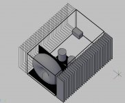
More easy is to mount the board on one heatsink because you have sufficient space, thus you can screw the IRF's directly on the heatsink using mica or polyimide sheets for electrical isolation.
The PSU you can mount flat on the bottom together with the rectifiers.
This is the way I have even assembled the stereo version in one case, without any thermal problem.
The PSU you can mount flat on the bottom together with the rectifiers.
This is the way I have even assembled the stereo version in one case, without any thermal problem.
I have a quick question about the 3rd set of Mosfets on the Peter Daniel board -
Does the total power dissipation go up, or is the same heat/power just shared amongst the extra devices?
And does the 3rd set increase the PSU current requirement?
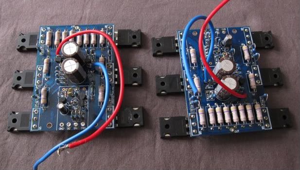
I got these boards few months ago, for a different project where I was going to cannibalize the boards and use them in my power j-fet Aleph. Since then I have acquired a set of virgin boards, and am just going to build a 'standard' Aleph J with this set.
Does the total power dissipation go up, or is the same heat/power just shared amongst the extra devices?
And does the 3rd set increase the PSU current requirement?
I got these boards few months ago, for a different project where I was going to cannibalize the boards and use them in my power j-fet Aleph. Since then I have acquired a set of virgin boards, and am just going to build a 'standard' Aleph J with this set.
I'm not familiar with exact schm ( critical values ) on which these pcbs are based , but rule is - whatever bias you have with 2 pairs , you'll increase it for 50% if you include 3-rd pair
if you want same dissipation (with 3 pairs comparing to 2 pairs ), you'll need to readjust values of resistors in Aleph CCS and also value of input Jfet drain resistor
if you want same dissipation (with 3 pairs comparing to 2 pairs ), you'll need to readjust values of resistors in Aleph CCS and also value of input Jfet drain resistor
Sorry for interrupting but I am curious.
I want to build standard aleph j(2 output pairs) with 1.6A bias for each fet.Do I have to readjust value of input Jfet drain resistor (R7) ?
if standard , they will have cumulative ~1A6 Iq , so ~800mA per each vertical pair
Yesterday I have drilled the holes for the mosfets in my heatsinks and i have managed to scratch one of them (heatsinks).The scratch is not very deep but when i attach the mosfet i have electrical conductivity 
Now my question is how could I cover the scratch so I could interrupt electrical contact?
One of the possibilities I thought is to use mica insulator but i will raise thermal resistance this way and it is not good.I have 2 mosfets on each heatsink and if I use mica insulator on one mosfet I guess I'll have to use mica insulator one the other mosfet too as well to keep junction temperature(dissipation) the same.Is that right?
The second thing that passes through my mind is to use a thicker thermal grease layer.Would this do the job?
Anyway how safe is to use anodisation as electrical insulator?
- Home
- Amplifiers
- Pass Labs
- Aleph J Schematic