I also bought some of those, but after testing them I returned them. The seller admitted to me that they are counterfeits but still claims they are very good jfets. Their parameters aren't even close to j74s.
Happy Holidays Everyone!
Not good news at all. Are you referring to the same ebay seller that I have mentioned....
Different seller, same product. I bought 60.
In theory can such mutant 2SJ74BLs (high IDSS types) exist? TIA.
Can I first test with a light bulb
I have used a light bulb in series to first power on my F5 earlier to ensure no wrong connections or short. Once I was clear, I would remove the light bulb and adjust the bias on F5.
How do I test a Aleph-J. Can I use a light bulb?. Since Aleph-J biases up on it's own (since there are no trimpots), will the light bulb not blow up for the high current draw?
Any suggestions will help.
Cheers.
Sure you can, the light bulb is the current limiter. Even if it's a dead short the bulb will only draw its rated current. You can start it up this way, but don't try to take any meaningful voltage readings, they will be all over the map. You need a variac for that.
Best, Bill
Best, Bill
Sure you can, the light bulb is the current limiter. Even if it's a dead short the bulb will only draw its rated current. You can start it up this way, but don't try to take any meaningful voltage readings, they will be all over the map. You need a variac for that.
Best, Bill
Thanks, I don't have a variac and I need to be happy a light bulb.
Cheers.
All you're looking for with the bulb is that it is NOT at/near full brightness. What you are checking with it is that there isn't a major fault in your amp's wiring. Use a 100+W bulb, a smaller bulb will burn too brightly at the F-5 current draw.
Thanks. I understand. In fact I have a 200w bulb. Btw I am looking to test a Aleph j and not a F5.
Cheers.
1V DC offset on my new Aleph J build
Just finished wiring up my pair of Aleph J boards. Test the boards through a 100w bulb circuit. Supply rails are +24.6V and -24.6 volts supplied through a standard Pass power supply design with a 600VA toroid.
I have shorted the + and - inputs to ground for testing purposes. Connected up a DMM to the speaker output. When powered on, the bulb lights up and dims a little bit and comes back to brightness (not full brightness). The speaker output measures little higher than 1V DC offset. I quickly turned off in may be 2-3 seconds. No smoke, no heating of any component.
Tested with the same process, the other board as well. Exactly the same behavior.
Rechecked all the polarities, solders, component values and IRF orientation. I can find nothing wrong.
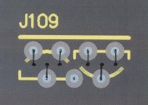
My suspicion is that - I have used instead of 2SJ109BL, a matched pair of 2SJ74BLs. However the IDSS of each of these matched 2SJ74BL is 17.6 mA, unusually higher than the sub 10mA ranges of 2SJ74. Can this be the reason. The circuit is 100% stock Aleph J (schematic corrected version of Mr. Pass). I have used the attached orientation for 2SJ74s instead of 2SJ109.
I have not used a trimpot instead of R8 for offset adjustment. I do not know whether it is the adjustment of R8 that is required or there is a fault in the circuit.
The IRFs are matched quartets from Tech-DIY.
Whatever is the fault, seems to be manifested in both the boards similarly.
Need help from the esteemed forum members please.
TIA.
Just finished wiring up my pair of Aleph J boards. Test the boards through a 100w bulb circuit. Supply rails are +24.6V and -24.6 volts supplied through a standard Pass power supply design with a 600VA toroid.
I have shorted the + and - inputs to ground for testing purposes. Connected up a DMM to the speaker output. When powered on, the bulb lights up and dims a little bit and comes back to brightness (not full brightness). The speaker output measures little higher than 1V DC offset. I quickly turned off in may be 2-3 seconds. No smoke, no heating of any component.
Tested with the same process, the other board as well. Exactly the same behavior.
Rechecked all the polarities, solders, component values and IRF orientation. I can find nothing wrong.
My suspicion is that - I have used instead of 2SJ109BL, a matched pair of 2SJ74BLs. However the IDSS of each of these matched 2SJ74BL is 17.6 mA, unusually higher than the sub 10mA ranges of 2SJ74. Can this be the reason. The circuit is 100% stock Aleph J (schematic corrected version of Mr. Pass). I have used the attached orientation for 2SJ74s instead of 2SJ109.
I have not used a trimpot instead of R8 for offset adjustment. I do not know whether it is the adjustment of R8 that is required or there is a fault in the circuit.
The IRFs are matched quartets from Tech-DIY.
Whatever is the fault, seems to be manifested in both the boards similarly.
Need help from the esteemed forum members please.
TIA.
Attachments
use trimpot+resistor , as input LTP CCS reference ;
put 500R trimpot in series with 680R resistor - instead of R8 (1K) in ZTX's emiter ;
if offset is positive , you need more current through LTP , meaning that you need smaller value than 1K there
R8 designation - looking at original Papa's Aleph J schematic
put 500R trimpot in series with 680R resistor - instead of R8 (1K) in ZTX's emiter ;
if offset is positive , you need more current through LTP , meaning that you need smaller value than 1K there
R8 designation - looking at original Papa's Aleph J schematic
1V DC offset on output
Anilva,
First, 1V isn't critical w.o. fine tuning.
Second, please replace R8 with a trim pot to try to adjust DC-offset close to zero.
Third, please check on the device front if the 2SJ74 is a BL or V type. Based on the data sheet the IDSS range for BL types is 6.0 - 12.0mA.
If the type printing show BL and the IDSS maesurement give 17mA, the device is a fake one and should be replaced.
Gerd
Thanks for the response. I was getting worried that my post is not getting any help!
OK, will first go and change the R8 with a trim-pot. Should I start with the trimpot set to max or min setting in terms of resistance?
The JFET is a BL variant and not a V type. I was sold that these are standard BLs but with high IDSS, come out of some stock. May be they are fake. I have regular BLs but they are not matched, but may be close to each other. I can try with them.
If there is a 1v DC offset, is there a chance that I fry some of the devices if I continue with the measurement and keep the power on?
Any other area to look at?
TIA?
The 1 volt offset is meaningless with the lightbulb in the circuit, and so would any other measurements you take. You can leave it on as long as you wish. You could check your rail voltages to see how much you have left with the lightbulb drop.
You have reached the point of determining how confident you are about your wiring and construction.
Good luck.
You have reached the point of determining how confident you are about your wiring and construction.
Good luck.
use trimpot+resistor , as input LTP CCS reference ;
put 500R trimpot in series with 680R resistor - instead of R8 (1K) in ZTX's emiter ;
if offset is positive , you need more current through LTP , meaning that you need smaller value than 1K there
R8 designation - looking at original Papa's Aleph J schematic
Thanks ZM. Yes, R8 as per original schematic. Will try with trimpot and report back.
The 1 volt offset is meaningless with the lightbulb in the circuit, and so would any other measurements you take. You can leave it on as long as you wish. You could check your rail voltages to see how much you have left with the lightbulb drop.
You have reached the point of determining how confident you are about your wiring and construction.
Good luck.
Thanks. I am very confident of my wiring and construction. Only doubts are on the offset resistor values, jfets and may be Zener. I don't have access to another set of jfets at the moment, will try the other two.
Getting there...
Removed the bulb in the circuit and fired the board again. The dc offset has come down from 1.05v to 270mv. Kept it on for sometime. No problem. Quite stable and the mosfets are getting hot as they should be. Supply rails measuring +/- 24.5v. I will tweak R8 with a trimpot and report back, so far no other change made.
Thanks for the help and advice.
Cheers.
Congratulations!
The trimpot might not do it with the counterfeit jfets in there, but it's worth a try.
It would be a good time to learn how to match jfets, it really is easy to match Idss.
I hope my JFETs are not counterfeit, but just freak high IDSS ones. Secondly i will start measuring IDSS and matching JFETs myself. I need to buy a bunch of these FETs for matching. Quite expensive though.
- Home
- Amplifiers
- Pass Labs
- Aleph J Schematic