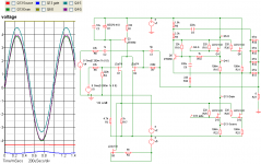
In the preceding schematics there's a blip that shows up in LU1014Ds drain voltage. It occurs when the sine-wave dips across its position on the graph. This blip seems to transfer to the cascode Mosfet. By lowering the setting on VR1 to 36 percent, I was able to lower LU1014Ds drain voltage below the bottom leg of the sine-wave and remove the blip.
thorstenlarsen said:Hi Carpenter !
To lower the current in the dif pair, you just have to put a resistor at the source of the SK 170. By ajusting the resistor value, you can ajust the current in the first leg of the dif pair.
Thorsten Larsen
Thanks Thorsten. It's similar to the power resistors on the right hand side of the amplifier, yes? Each bank has a resistor. I should have realized..... I remember staring at the SK170 and wondering if there should be additional resistance. Excellent.
It's a good feeling to know that the members of this forum look out for one another.
")
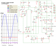
This one's just for fun (and strickly for my 110 db 1W1M horns)... the power through the LU1014Ds is around 33 watts each (a bit high, wouldn't you say ) and drastic means are required to remove the excess heat. I wonder how it would sound?
Pointless? Maybe.
Still, it's a fun exercise.
) and drastic means are required to remove the excess heat. I wonder how it would sound?Pointless? Maybe.
Still, it's a fun exercise.
Attachments
carpenter said:This one's just for fun (and strickly for my 110 db 1W1M horns)... the power through the LU1014Ds is around 33 watts each (a bit high, wouldn't you say
Pointless? Maybe.
Still, it's a fun exercise.
that output CCS is rotten

remember - biasing of LU is same as for triode , or any little N Jfet ;
Zen Mod said:remember - biasing of LU is same as for triode , or any little N Jfet ;
Do you mean it's self-biasing with only a source resistor? Kinda like JfetBOZ?
carpenter said:
Do you mean it's self-biasing with only a source resistor? Kinda like JfetBOZ?

(sometimes it's wise - if nothing else - to simulate simplest circs , just to have idea how they function
 )
)carpenter said:I dropped the extra current source, added a cap between LTP and power jfet's gate--to let the jfet bias itself. Lost the sine-wave.
you lost ME there , too
you can't drop CCS - its working LOAD for output Jfet ;
in fact - which CCS you dropped - additional one ( hangin' on drain of input Jfet) or output CCS ?
gimme that schematic , and somebody will tell you wher eis mistake
Zen Mod said:
you lost ME there , too
you can't drop CCS - its working LOAD for output Jfet ;
in fact - which CCS you dropped - additional one ( hangin' on drain of input Jfet) or output CCS ?
gimme that schematic , and somebody will tell you wher eis mistake
Do you get anything out of that sim? Just curious
Naah, if you wanna play that game, better optimize the CCs instead.
And for Choky, read your mail!!!
Magura
You ll be disapointed but ...Magura said:And for Choky, read your mail!!!
Choky never read his own post ...
Manu said:
You ll be disapointed but ...
Choky never read his own post ...
Yeah, I ought to know

Magura
Carpenter, you need to ground reference the gate. I don't know why you don't simply read the posts you were linked at; you could avoid all these simple things.
Have fun, Hannes
EDIT: oh and I forgot: maybe you want to read a bit about differential pairs as well? Then you probably don't want to remove its tail current source.
Have fun, Hannes
EDIT: oh and I forgot: maybe you want to read a bit about differential pairs as well? Then you probably don't want to remove its tail current source.
Magura said:
.......
And for Choky, read your mail!!!
Magura
who's that pooftaaah - Choky ?

- I didn't received any e-mail from you these days
h_a said:Carpenter, you need to ground reference the gate.
Which gate?
Zen Mod said:
give us last schematic
I don't know which one h_a was referring to...
That's why I asked.
carpenter said:
I don't know which one h_a was referring to...
That's why I asked.
I adore that usual game with you ....... where we all chasing own tales ......
give us last schematic you tried , with comments
- Home
- Amplifiers
- Pass Labs
- Aleph J Schematic