humble ZM ....... risking public humiliation again

just a idea .........
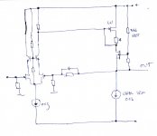
need few tests for deciding exact number of leds in input jfet source ;
CCS in source of output jfet - what else than Papa's 240 thingie
Papa ........ ?
is it newest see-saw machine?
just a idea .........
need few tests for deciding exact number of leds in input jfet source ;
CCS in source of output jfet - what else than Papa's 240 thingie
Papa ........ ?
is it newest see-saw machine?
Attachments
EUVL said:...........
Hang a 4mA constant current diode (e.g. J511) from each of the drains of the JFET diff pair to 10V below the negative rail.
The rest I should leave as mental jogging exercises.
Patrick
good one
")
First : A year ago my old amp broke down and I didnd got started building my own one. I wanted to hear music and so I byed an Aleph J from Reno Hifi. I love this Amp It dond need any canges. It´s an Amp from Heaven.
But I had the following ideas:
Using 3 or 4 pairs of output Transistors ( more Damping Factor and better Head spreading)
Using the J Fets with higher output currend ( I think it was GR grade, or was it V ? anyway ) to drive the extra pair.
Bias the hell out of it ( of cours with bigger PSU and Head sinks)
The goal could be much more Power for 4 ohm Speakers. ???
Bernhard
It dond need any canges. It´s an Amp from Heaven.But I had the following ideas:
Using 3 or 4 pairs of output Transistors ( more Damping Factor and better Head spreading)
Using the J Fets with higher output currend ( I think it was GR grade, or was it V ? anyway ) to drive the extra pair.
Bias the hell out of it ( of cours with bigger PSU and Head sinks)
The goal could be much more Power for 4 ohm Speakers. ???
Bernhard
> Using 3 or 4 pairs of output Transistors
See post #215 & #217.
PS
One more tipp from me. If you use a Grade V JFET (Idss 16mA) for the diff pair, and change the drain resistors to 500 ohm, you can drive at least 3 pairs of 2SK1529 directly (without additional follower) without losing any bandwidth. Transconductance of 2SK1529 is comparable to IRFP240. They do sound different -- matter of taste.
By changing the resistor to 500R, you will reduce the open loop gain of the 1st stage by 50%, and hence also the amount of negative feedback.
Patrick
EUVL said:> just a idea .........
No, no. You need to come up with something more elegant.
Patrick
One could use a separate, more negative supply on the 'J109's drain R, maybe just hooked off with a zener or TL431...sandmarc said:I was thinking about building the output stage with Lu1014Ds cascoded with the IRFP240s.
- Klaus
Dr. ODD said:First : A year ago my old amp broke down and I didnd got started building my own one. I wanted to hear music and so I byed an Aleph J from Reno Hifi. I love this Amp
But I had the following ideas:
Using 3 or 4 pairs of output Transistors ( more Damping Factor and better Head spreading)
Using the J Fets with higher output currend ( I think it was GR grade, or was it V ? anyway ) to drive the extra pair.
Bias the hell out of it ( of cours with bigger PSU and Head sinks)
The goal could be much more Power for 4 ohm Speakers. ???
Bernhard
EUVL said:> Using 3 or 4 pairs of output Transistors
See post #215 & #217.
PS
One more tipp from me. If you use a Grade V JFET (Idss 16mA) for the diff pair, and change the drain resistors to 500 ohm, you can drive at least 3 pairs of 2SK1529 directly (without additional follower) without losing any bandwidth. Transconductance of 2SK1529 is comparable to IRFP240. They do sound different -- matter of taste.
By changing the resistor to 500R, you will reduce the open loop gain of the 1st stage by 50%, and hence also the amount of negative feedback.
Patrick
This is the approach I was thinking of taking to bias more power into 4 ohms. Using a V grade jfet from the GB and irf 150 or 250's for the FET's.
-David
> One could use a separate, more negative supply on the 'J109's drain R, maybe just hooked off with a zener or TL431...
Doesn't any ripple voltage (or noise) between this "more negative supply" and the "normal" negative rail gets directly magnified in the 2nd stage, i.e. 0dB PSRR ?
Patrick
Doesn't any ripple voltage (or noise) between this "more negative supply" and the "normal" negative rail gets directly magnified in the 2nd stage, i.e. 0dB PSRR ?
Patrick
Yes... so the dropped supply must be very clean. I think a shunt reg, properly bypassed to R18/19, would do it. With adjustable offsetting one could also optimize the LTP current and output offset independently, even open-loop gain (via R7). Not shure if this would still be an Aleph-J, though.
- Klaus
- Klaus

sandmarc said:very interesting and very promising so far.
keep it up.
SandMarc
yup-as follower .........

> another brilliant idea
> I forgot that I need P type LU for that
I am stupid this morning.
Explain to me how you might get +1V Vgs on your P-type LU (or if you flip it, then -1V Vgs on LU1014) to get the triode curve ?
> keep it up.
It is perhaps time you get your own brain to do some work ......
Patrick
> I forgot that I need P type LU for that
I am stupid this morning.
Explain to me how you might get +1V Vgs on your P-type LU (or if you flip it, then -1V Vgs on LU1014) to get the triode curve ?
> keep it up.
It is perhaps time you get your own brain to do some work ......
Patrick
EUVL said:> another brilliant idea
> I forgot that I need P type LU for that
I am stupid this morning.
Explain to me how you might get +1V Vgs on your P-type LU (or if you flip it, then -1V Vgs on LU1014) to get the triode curve ?
> keep it up.
It is perhaps time you get your own brain to do some work ......
Patrick
Patrick
I know that you are stupid , so there is no need to say that in public ;
for me - name of the game is fun , not "smartyfarty" ;
I'm not here for contest .
you are looking at trivia in that schmtc , even if entire schmtc is trivial
> I know that you are stupid , so there is no need to say that in public
I have no problem admitting that in public.
> I'm not here for contest
Neither am I.
It was a legitimate question.
The entire difficulty of using LU1014 in the circuit IS the negative Vgs.
I had a second look just now and still could not figure out how your proposal would solve that.
So perhaps you can enlighten me.
Patrick
EUVL said:> I know that you are stupid , so there is no need to say that in public
I have no problem admitting that in public.
> I'm not here for contest
Neither am I.
so - welcome to the club of smart ones , so we can continue with fun......
It was a legitimate question.
The entire difficulty of using LU1014 in the circuit IS the negative Vgs.
I had a second look just now and still could not figure out how your proposal would solve that.
So perhaps you can enlighten me.
Patrick
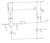
it was legitimate question , but it was also more than obvious that I made mistake connecting G-S of LU ( that line probably was just intention to draw bracket for pointing voltage G-S , or just brain glitch ..... whatever )
input LTP is nothing else than tube LTP and LU is nothing else than top tube in output tube cascode ........biasing LU is achieved with biasing input LTP ......... pretty common way of DC coupling two stages in tube world ........
anyway - nothing of that is important really ; what is - is that I drew follower with LU , not active stage ......
it can be done like this , but with full swing stage in middle , and I don't wanna do that.
Attachments
Choky,
I think you are still missing my point.
Put the +ve rail on the bottom, and you almost get back to Nelson's schematics.
The voltage across the drain resistor of the diff pair is something like 4V ABOVE negative rail. If we stick to a source resistor of 0R68 for the LU1014, AND you want it to work in the triode region, then the current through the 0R68 is something like (4+1)V/0R68 = 7.3A. That is likely to kill your 1014.
In ZV9, the gate of the 1014 is at 0V nomimal. But because there is a bias of about 1.3A, the 0R68 will have 1V drop across it, makeing the source at 1V nominal. Thus, Vgs is about -1V.
Any modification of the A-J schematic to use the 1014 has to be able to offer this -1V Vgs before it will work as intended. My proposed solution with the 4mA CCS diode is intended to drain all the DC current of the diff pair so that there is no DC current across the drain resistors, i.e. Vg at negative rail voltage. The rest is then like ZV9, but referenced to the negative rail.
Hope we are still not talking over each other.
Patrick
- Home
- Amplifiers
- Pass Labs
- Aleph J Schematic