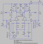
I'm working on integrating the Pass D1 I/V to my AD1955 DAC. I'm first experimenting with SPICE sims as an educational tool to learn more about how this circuit operates.
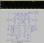
In the sim, I was able to adjust the sources of Q3 & Q5 to within +-44mv. The offset is -28mv.
How would someone adjust this 28mv offset to 0?
Thank you!
-David
In the sim, I was able to adjust the sources of Q3 & Q5 to within +-44mv. The offset is -28mv.
How would someone adjust this 28mv offset to 0?
Thank you!
-David
Attachments
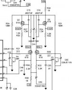
I've changed the values of R26 and R33 from 3K3 to 4K7. The offset was reduced to -2.35mv.
Are these the correct resistors to adjust?
Like the first post, the measurements are from the Sources of Q3 and Q5. In simulation this was the closes to zero thta could be obtained.
Any thoughts or comments are appreciated.
Thank you!
-David
Are these the correct resistors to adjust?
Like the first post, the measurements are from the Sources of Q3 and Q5. In simulation this was the closes to zero thta could be obtained.
Any thoughts or comments are appreciated.
Thank you!
-David
Attachments
OK one last sim...
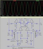
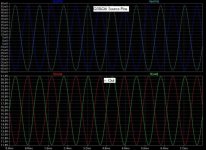
R26 & R33 adjusted to 4K7, and P4&P5 are tuned perfectly as well. The offset is now perfectly adjusted, however there is one side effect.
In the attached plot, the amplitude is higher above zero than below. Any ideas on what could cause this behavior?
Thank you!
-David
R26 & R33 adjusted to 4K7, and P4&P5 are tuned perfectly as well. The offset is now perfectly adjusted, however there is one side effect.
In the attached plot, the amplitude is higher above zero than below. Any ideas on what could cause this behavior?
Thank you!
-David
Attachments
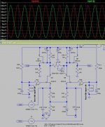
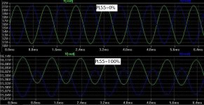
The offest issue is fixed, but the issue of the amplitude above offset for Q3&Q6 Source pins is unbalanced with a higher amplitude above the cross-over point.
Here's a larger plot that shows the I/V MOSFET Source pins and the output waveform of the buffer MOSFETs Q2 & Q5.
Is is expected behavior or is there something wrong?
Thank you,
-David
Here's a larger plot that shows the I/V MOSFET Source pins and the output waveform of the buffer MOSFETs Q2 & Q5.
Is is expected behavior or is there something wrong?
Thank you,
-David
Attachments
- Status
- This old topic is closed. If you want to reopen this topic, contact a moderator using the "Report Post" button.
- Home
- Amplifiers
- Pass Labs
- D1 Offset Questions