Hello everybody,
sorry to bug you guys, but i am having an issue with the Aleph P and, if possible,i would need your support.
I 'am softly firing this circuit up by using a variac.
Until the power supply is below 50V everything seems to behave ok.
The voltages on the 10uf and 30uf output cap were approaching to 14V and 29V respectivetly.
The Vce on Q12, Q13, Q14, Q15 was correctly at 4.5V and so was the VBE at 0.6V.
Nevertheless, when i go a little higher than 50V, the 22ohm resistor (which i'm using 23.5 in place of 22) blows up.
At that point, i've registered about 8.5V on the VDS of Q15, Q18.
Sincerely, i think it should have been at least to 20V, don't know if i'm wrong.
I have re-checked all the connections and possible faults on the board, but everything seems (but it obviously isn't") ) to be ok.
) to be ok.
I have checked the semiconductors with the meter and they seemed to be ok.
I'll try to put the irf610 on the power supply and see if they work.
(By the way is it enough to check the mosfets with a meter in order to find out if they are broken or not?)
I don't know if this could be a usefull data: i'm using, instead of the ztx 450 - ztx550, the BC337 and BC327.
Hope to figure this out with your help.

Thanks a lot in advance for the efforts.
Best,
Stefano.
sorry to bug you guys, but i am having an issue with the Aleph P and, if possible,i would need your support.
I 'am softly firing this circuit up by using a variac.
Until the power supply is below 50V everything seems to behave ok.
The voltages on the 10uf and 30uf output cap were approaching to 14V and 29V respectivetly.
The Vce on Q12, Q13, Q14, Q15 was correctly at 4.5V and so was the VBE at 0.6V.
Nevertheless, when i go a little higher than 50V, the 22ohm resistor (which i'm using 23.5 in place of 22) blows up.
At that point, i've registered about 8.5V on the VDS of Q15, Q18.
Sincerely, i think it should have been at least to 20V, don't know if i'm wrong.
I have re-checked all the connections and possible faults on the board, but everything seems (but it obviously isn't
) to be ok.I have checked the semiconductors with the meter and they seemed to be ok.
I'll try to put the irf610 on the power supply and see if they work.
(By the way is it enough to check the mosfets with a meter in order to find out if they are broken or not?)
I don't know if this could be a usefull data: i'm using, instead of the ztx 450 - ztx550, the BC337 and BC327.
Hope to figure this out with your help.
Thanks a lot in advance for the efforts.
Best,
Stefano.
Just another information, maybe can be usefull:
The VCE max for the BCs is rated at 50V (zetex at 60V).
I just tried to simulate the behaviour of the circuit throughout pspice simulator.
The end of the result is, by using a linear ramp as power supply, that the voltage across Collect Emettitor of Q14-Q15 rises up to 59V till it conducts and from then the voltage goes down to 4.5V.
That would justify the fault of the circuit at 52V (VCE of Q14 rises up over the threshold rated limit for the BC).
Even so, i still don't understand how it can affect the R44 resistor ...and especially just that one.
Hello Stefano,
just one idea.
Did you recognize that collector and emitter on the bc 327, bc 337 packages are exchanged compared to the ztx450, ztx 550 pins? You have to turn the bc´s 180 degrees to make them work properly in the given P1.7 circuit layout.
best regards
Oliver
just one idea.
Did you recognize that collector and emitter on the bc 327, bc 337 packages are exchanged compared to the ztx450, ztx 550 pins? You have to turn the bc´s 180 degrees to make them work properly in the given P1.7 circuit layout.
best regards
Oliver
Stefanoo said:nobody have a clue?

stefano- pictures
without them , all we talk is just little more than gossip
Stefanoo said:Hello everybody,
I don't know if this could be a usefull data: i'm using, instead of the ztx 450 - ztx550, the BC337 and BC327.
I thought that the ZTX450 is equivalent to the BC550C and the ZTX550 is equivalent to the BC560C.
Just my 2 cents ....
Fox
Zen Mod said:
stefano- pictures
without them , all we talk is just little more than gossip
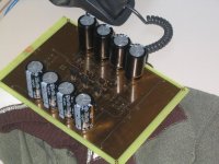
Well all the components on the board are now unmounted 'cause i'm checking for eventual faults on the tracks (since i didn't have through metal hole board the solderings on the top probably had cause some problems and now i'm trying to re-mount everything back paying the maximum care!...the final board will be with rivets that i have bought).
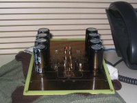
I have a couple of pictures of the board when i was still mounting some of the parts on...
here the first ..
Attachments
Fox said:ZTX450 equivalent to the BC550C, ZTX550 equivalent to BC560C.
Not if you look at a datasheet.
Trivia : the 450/550s are pretty old devices, not even a Zetex development. but something ZTX swalllowed.
jacco vermeulen said:
Not if you look at a datasheet.
Trivia : the 450/550s are pretty old devices, not even a Zetex development. but something ZTX swalllowed.
but Papa will have few survived from his pile ,even after biiiiiiig bada-boom
ZLeeloooM ........... multipass.......
Sorry guys, But i haven't understood anything of what you guys were trying to say.
Are the BC327/337 equivalent to the ZTX450-ZTX550?
If not: why?
Accordingly with what i have simulated with PsPice everything should go allright with this transistors.
The only thing that makes me wonder is the VCE MAX for the 337/327 (50V) that is the same of BC550/560.
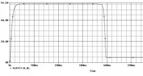
I attached the simulation results by using a ramp as a power rail voltage, shoring the input and mesuring the voltage on Q14.
Are the BC327/337 equivalent to the ZTX450-ZTX550?
If not: why?
Accordingly with what i have simulated with PsPice everything should go allright with this transistors.
The only thing that makes me wonder is the VCE MAX for the 337/327 (50V) that is the same of BC550/560.
I attached the simulation results by using a ramp as a power rail voltage, shoring the input and mesuring the voltage on Q14.
Attachments
- Status
- This old topic is closed. If you want to reopen this topic, contact a moderator using the "Report Post" button.
- Home
- Amplifiers
- Pass Labs
- problem with R44 on Aleph P 1.7