Hello everybody!
In this past days i have been trying to fire the power supply up but without successing!
I don't know what's the problem, the wiring seems to be correct.
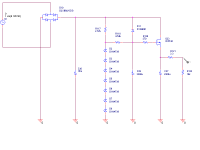
I have attached the schematic that i've used for the power supply which it uses the same refereces as Nelson Pass original's schematic.
Here is the problem:
Nevertheless i get the correct value at the output of the pile of zeners of about 63.8V (insteat of using 7 9.1V i have used 2 32V zeners), the output of the circuit on R122 only goes up to 44.3V.
I would also expect the voltage across R118 to go down to 0V after C29 charged up, instead, after like 20 seconds the voltage stayies steady at 18.8 V.
V Gate-Source instead of being 4V is 61V.
Therefore, at certain point, i thought i made a mistake on the IRF pinout.
I tried to swap the two pins: gate and source, but the output voltage hasn't gotten any better (about 43.3V).
Can anybody conferm me if the pin out drawn here for the irf 610 is correct or not?
(it's drawn from the front view)
----------
| O |
----------
|IRF610|
| |
---------
| | |
| | |
G D S
The transformer i use gives me 105V after the rectifier and C30.
Hope to fix this problem and step on firing the aleph board.
Thanks in advance for the hints.
Best,
Stefano.
In this past days i have been trying to fire the power supply up but without successing!
I don't know what's the problem, the wiring seems to be correct.
I have attached the schematic that i've used for the power supply which it uses the same refereces as Nelson Pass original's schematic.
Here is the problem:
Nevertheless i get the correct value at the output of the pile of zeners of about 63.8V (insteat of using 7 9.1V i have used 2 32V zeners), the output of the circuit on R122 only goes up to 44.3V.
I would also expect the voltage across R118 to go down to 0V after C29 charged up, instead, after like 20 seconds the voltage stayies steady at 18.8 V.
V Gate-Source instead of being 4V is 61V.
Therefore, at certain point, i thought i made a mistake on the IRF pinout.
I tried to swap the two pins: gate and source, but the output voltage hasn't gotten any better (about 43.3V).
Can anybody conferm me if the pin out drawn here for the irf 610 is correct or not?
(it's drawn from the front view)
----------
| O |
----------
|IRF610|
| |
---------
| | |
| | |
G D S
The transformer i use gives me 105V after the rectifier and C30.
Hope to fix this problem and step on firing the aleph board.
Thanks in advance for the hints.
Best,
Stefano.
Attachments
first- with just two zenners in chain you'll have too much dissipation in them
do not let ever more than 5mA through zenner ; common practice,at least for me.
recalculate that resistor (2K57) according to that ;
everything else in schmtc looks OK , culprit is probably in exact physical layout
do not let ever more than 5mA through zenner ; common practice,at least for me.
recalculate that resistor (2K57) according to that ;
everything else in schmtc looks OK , culprit is probably in exact physical layout
63.8V at the top of D2 minus 18.8V across R118 is 45V, corresponds with the output voltage.
Looks to be working, the 4mA currentflow through R118 seems to suggest a leaking capacitor.
Tried exchanging C29 ?
(iiwy i'd stick to exact design component values and rail voltages for the time being)
GDS is the standard pin sequel for non-Japanese MOSFETs, Japanese devices and stuff like Magnatec clones have GSD pinning.
Thanks.
Apparently the zeners are not overheating.
I'll change the resistor next to give them the right amount of current.
Eather way that is not the problem since i get anyways the right voltage, as i said, out of the pile of zeners.
Is the pinout correct?
I don't understand, this Mos are form IRF so i would expect the standard GDS pin out, correct?
If i unconnect the MOS Q23, C29 as expected, charges up to 64V, so C29 is not broken, i guess.
Could it be the mos that is damaged? or i don't know...i'm certainly saing a dumb thing but:
should i solder the mos with an electrostatic pad???....i'm totally guessing thought!
I don't know...i have triple and more checked the wiring, conncetions....eventual faults...and so on....
Please helpppp
")
- Status
- This old topic is closed. If you want to reopen this topic, contact a moderator using the "Report Post" button.