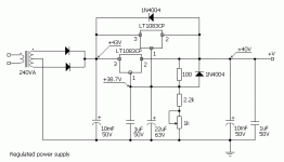
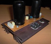
This is the power supply regulator I made for my class-a "Krypton" amplifier and it works great!
Ripple before regulator is 1V and afer regulator 100uV with the 2A load!
Sounds great to.
Note: Regulators must be matched, or you have to connect balast resistors on the regulators output(0.1 Ohm is enough).
Ripple before regulator is 1V and afer regulator 100uV with the 2A load!
Sounds great to.
Note: Regulators must be matched, or you have to connect balast resistors on the regulators output(0.1 Ohm is enough).
Attachments
Banned
Joined 2002
Hi Jason,
I think the input - output voltage is far too close. It will probably drop out when the line voltage drops a little. I don't know what the line regulation is like in Europe where Bogdan is, but here in North America the line variation is too high for this circuit. Add to the fact that the step down ratio is 1/2 what Bogdan's transformer is ...
Nope.
How much current does each channel draw?
-Chris
Banned
Joined 2002
anatech said:Hi Jason,
I think the input - output voltage is far too close. It will probably drop out when the line voltage drops a little. I don't know what the line regulation is like in Europe where Bogdan is, but here in North America the line variation is too high for this circuit. Add to the fact that the step down ratio is 1/2 what Bogdan's transformer is ...
Nope.
How much current does each channel draw?
-Chris
depends on the bias, i think mine are all set at 1amp per channel.
Hi Jason,
Okay, your dissipation will be that current times the voltage drop. I imagine you want one regulator per channel.
Measure your highest AC voltage and your lowest. Add the dropout voltage and some safety factor plus the ripple trough. This will be your worst case voltage drop. Multiply that by the current and this is how much heat you have to get rid of.
-Chris
Yes anatech you`re right, I`ll raise the dropout voltage on the regulators for the worst case scenario,I didn`t have time to experimetn a lot but, i`ll send my conclusions soon.
The atached schematic is for one channel only, becouse my amplifier will be "dual mono". In my case only one regulator could do the work but I decided to parallel two regulators, just to be shure...
My amplifier bias is 2A and the peak current is 4A.
This kind of regulated supply makes bass more "dynamic", that`s my firs impression.
Will reply soon. Cheers!
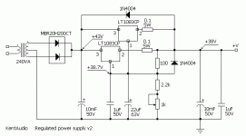
Banned
Joined 2002
anatech said:Hi bogdan,
Yep, that will work as well.
-Chris
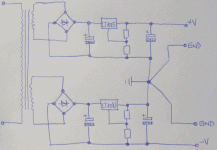
This was similar to what i was working on too, however i was not able to find a regulator that would be good for a steady 2amp draw for 2 aleph mini's, would having a regulated psu help at all ?
Anatech ?
Hi Jason,
I would normally design my own regulator for the task at hand. I haven't used three terminal regulators in a long, long time.
A 2 amp continuous design isn't very difficult. You need to decide how much headroom you want and how much noise you can live with. Is a little drift allowable? Voltage(s).
The biggest error people make is under estimating the amount of power the components dissipate. Remember that your "in case" temperature may run around 50°C and not the 25°C figures people like to use, so learn how to derate your parts for temperature. This may also create extra drift. Even your resistors may require holes in the PCB. After derating, your 1W resistor requirement may turn out to be a three or five watt part. Do not forget the influence of other warm parts near by.
Most people like to design very small circuit boards. I find some extra space can do wonders for reliability.
To do this the easy way, you could use an LM317 and LM337 (negative) regulator chip and simply boost the current capacity with an external transistor or two. I believe this is shown on those data sheets. Remember, try to run stuff as cool as you can.
-Chris
- Status
- This old topic is closed. If you want to reopen this topic, contact a moderator using the "Report Post" button.
- Home
- Amplifiers
- Pass Labs
- LT1083 PS-regulator for class A amps