Hi all,
I just completed my first NP project unfortunately I need a little help. I measured the voltages as indicated on the board and 2 of 4 are No Good, both channels have the same issue, therefore I am sure I did something wrong!
Q3 - Ok - 27V (a little high)
Q4 - NG - 28V (should be 13.8)
Q5 - NG - 28V (should be 11.7)
R8 - OK - 29V
Any suggestions would be greatly appreciated.
Regards,
Pathmark
Still need help!
Hi all,
I was wondering if anyone has any suggestions. Again, problem appears in both boards therefore I can imagine it is some mis-build but not sure where to look.
Both Q4-Q5 are reading 28V which is not correct according to NP article. Q3 and the regulated voltage of r8 are OK. I have posted a picture of boards.
Pathmark
Attachments
")
Sorry if the picture is not clear but the boards are identical to the NP boards from the Pearl article. I guess I am looking for more troubleshooting help on possible causes.
Again I have taken more measurements according to the NP article and none of the voltages after the regulation stage are correct.
Per the the schematic, all voltages on 2SK shoud be around 0.04 -0.07v but I am reading 29V.
So I guess I am trying to understand how that voltage can exist througout the board. It seems as though Q4-Q5 are are not doing anything. If orientation is correct is there anything else that can be wrong?
Pathmark
If the source voltages on all your J-FETs are reading 29 volts, then I don't see what it could be than a grounding issue. If you're using those boards from Prometheus, I think there's a ground jumper you gotta install. Have you installed that?
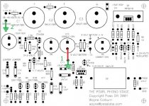
Kinda OT, but both the schematic, article and artwork? are the work of Wayne Colburn. Credit where it's due.
Kinda OT, but both the schematic, article and artwork? are the work of Wayne Colburn. Credit where it's due.
thanks for reply greyhorse, I was aware that this design was by Wayne I should have said Pass Labs not NP.
As for the grounding, I guess I am not sure about ground jumper. I do have the ground indicated in the center of the board tied to a star ground on the chassis.
Is this the jumper to which you refer or is there another?
Pathmark
As for the grounding, I guess I am not sure about ground jumper. I do have the ground indicated in the center of the board tied to a star ground on the chassis.
Is this the jumper to which you refer or is there another?
Pathmark
Take a look at the picture attached to post #10 on the following thread.
http://www.diyaudio.com/forums/showthread.php?postid=1247997#post1247997
Notice the white line just below C15? That line shows where there should be a jumper that connects the power supply section of the board to the amplifier section. There's even an arrow pointing to it with the caption "Connect Grounds here with a soldered wire". If you haven't installed that jumper, the amplifier section of your board has no potential difference across it. Since you have no current draw, everything is reading 29V with respect to your power supply ground.
As long as your PCB -IN connection also goes to your star ground, or if your PCB -IN connection goes to your input connector ground you should be good. All we need is for some ground on the amplifier section of your board to connect to the ground in the power supply section of the board.
If your problem turns out to be the grounding, connecting all those grounds at your star ground will get you going, but there's no guarantee it will be running optimally. A star ground is usually the simplest, most sure fire way of getting acceptable results, but in a lot of cases it's not going to get you the best performance depending on your goals. If you don't install that jumper directly on the PCB, you've already modified the original layout of the PCB, probably for the worse. Because the currents running through a phono preamp are small, your problems should be minimal though.
If your problem turns out to be the grounding, connecting all those grounds at your star ground will get you going, but there's no guarantee it will be running optimally. A star ground is usually the simplest, most sure fire way of getting acceptable results, but in a lot of cases it's not going to get you the best performance depending on your goals. If you don't install that jumper directly on the PCB, you've already modified the original layout of the PCB, probably for the worse. Because the currents running through a phono preamp are small, your problems should be minimal though.
greyhorse,
it really sucks being a newbie, thanks for your continued replies. So as of tonight, the issue is definitely related to grounding.
I thought I had a good scheme as follows:
PSU gnd --> star gnd
Phono gnd --> star gnd
PCB gnd Left hand--> star gnd
PCB gnd Right hand --> star gnd
Unfortunately I somehow have 28.x volts on the ground plane. If i measure any point from psu -in to anywhere on the PCB which should be zero I get 28.x volts.
If I measure from psu -in to star gnd I also get 28.x volts, clearly this is the problem. What I do not understand is where this value is coming from or how to get rid of it.
When I remove the PSU gnd from the star gnd I can measure 0 volts and I can measure 28.x volts on the PCB gnd. I thought by connecting these two together I would gnd the PCB but instead the star gnd goes to 28.x volts.
Any thoughts here would help.
Pathmark
I might sound like a broken record, but that jumper still looks to be the cause. You can get around putting the jumper directly on the PCB by doing the following:
PCB GROUND Left => Star Ground
PCB GROUND Right => Star Ground
PCB - IN Left => Star Ground or PAD 7 GND Left => Star Ground
PCB - IN Right => Star Ground or PAD 7 GND Right => Star Ground
Phono Ground => Star Ground
Star grounding the PSU grounds are redundant, as they are at the same potential as your PCB GROUNDs. It doesn't hurt to have this connected to your star ground though.
As for your choice of using PCB - IN or PAD 7 GND, Wayne recommends using the PAD 7 GND, I recommend the other, but that's just me.
Basically what I'm saying is that there are 2 grounds on the PCB that have to be joined together. You happen to be doing that at the star ground. It's very unconventional designing a PCB this way, which is why you're getting so confused, but I'm sure it makes sense for something.
The jumper in question is the one I've drawn in red. You are already trying to jumper those grounds together by connecting grounds 1 and 2 together at the star ground.
Now I can see ground 1 definitely goes to the star ground.
Now for ground 2. It appears you already have a wire connecting the PSU ground to the star ground, and if this is the case, then everything should be working... Do you think you could measure the resistance between grounds 1 and 2? If there is basically no resistance, than it probably isn't a grounding issue.
Just looking at the pictures, I'm getting a little concerned I've led you astray. If so, then you have my most sincere apologies.
Attachments
greyhorse,
we have a winner! holy cow thanks for sticking with me on this one. I guess I should have taken a picture of the underside. I just did not get that the jumper in the center needed to be connected to the negative of cap.
It was the final tip you mentioned about resistance between gnd in and center gnd should be zero.
Anyway I am happily listening to Coltrane right now. Thank for your help. Of course huge thanks to Wayne and NP for their dedication to DIY community.
Pathmark
- Status
- This old topic is closed. If you want to reopen this topic, contact a moderator using the "Report Post" button.
- Home
- Amplifiers
- Pass Labs
- Need some Pearl help - no sound!