Hi,
Here my Pass Aleph 2 and UGS diy
A2 :
Expensive Heatsinks from Seem-Semrac
Size : 300 x 200 x 75 mm with 19 mm base plate
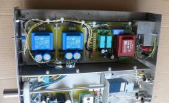
PSU
Transformer 2x35V 1KVA (local manufacturer)
Two rectifiers with MUR3020WT Onsemi
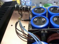
22000µf - 2,2mH – 2 x 22000µF - 4,7µFMKP (63V electrolytic caps)
U=49 V (more than 45V of original schematic).
BIAS is adjusted to 2.8A to keep heatsinks under 60°C.
Offset adjusted to 0mv (+/- 0,3mV) with R11 (thanks Cheff !") )
)
I used some audio parts : 220µF capacitors Elna Silmic II, MOX4 resistors and Kiwame resistors but I can’t say if it sounds better because I don’t test standard ones.
PCB from PCB-Design
ZTX 450 instead of MPSA18 (I don’t know why, I have MPSA too but I don’t test)
DC protection and delay 6s with a Velleman K4700 kit.
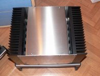
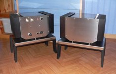
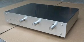
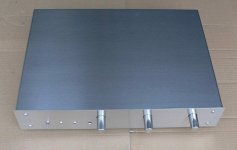
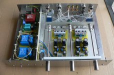
The blocks (37 kg each) are built with polish stainless steel. An “U” prevents electronics parts from hot temperature. In fact, heatsinks are out of the box --> 55-60°C max for heatsinks, 24-26°C max inside, better for capacitors’ life time (I hope).
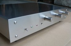
UGS : Exactly as proposed by Cheffdegaar here.
I simply used Cheff’s prototype PCB and added a mechanical selector and 4x10Klog ALPS potentiometer at output. Cheff gives all is necessary to built one easily (schematics, pcb draw … and help too). Just one difficulty: to find the Toshiba Jfet!
I put a second potentiometer in case of balance adjustment becomes necessary (not used actually).
It’s difficult for me to describe the sound in English. UGS and Aleph2 give wonderful results. Natural sound, a lot of details, marvelous rhythm based on deep and rapid bass and lovely high frequencies. The power reserve is appreciable too and I sometimes use no reasonable volume level . Very pleasant I find!
A heating period, 45min-1hour minimum is needed to get the best results.
Unfortunately, all is not perfect :
- Sometime the big toroïds make variable bzzzzz like neon tube lights. I tried to intercept a 230V-230V transformer between wall connect and amps but the bzzzz continues. I tried a DC-blocker too but without result. I suppose the noise is not due to DC inlet. The transformers are probably bad quality, I suppose.
- The heatsinks get very warm of course (55-60°C) and my little room (15 m²) becomes slowly a sauna when the amp runs a long time. So I can’t use this amp during summer, too uncomfortable .
.
I regret not insert standby mode (reduced BIAS) and not to limit the power to 50W (Aleph 5 for example instead of 2).
I have to find another solution for summer, built a cold amp later …
I sincerely thank Mr. Pass for generosity and the quality of his amps.
Thanks Cheffdegaar too and others guys for precious advices and help
Laurent
Here my Pass Aleph 2 and UGS diy
A2 :
Expensive Heatsinks from Seem-Semrac
Size : 300 x 200 x 75 mm with 19 mm base plate
PSU
Transformer 2x35V 1KVA (local manufacturer)
Two rectifiers with MUR3020WT Onsemi
22000µf - 2,2mH – 2 x 22000µF - 4,7µFMKP (63V electrolytic caps)
U=49 V (more than 45V of original schematic).
BIAS is adjusted to 2.8A to keep heatsinks under 60°C.
Offset adjusted to 0mv (+/- 0,3mV) with R11 (thanks Cheff !
)I used some audio parts : 220µF capacitors Elna Silmic II, MOX4 resistors and Kiwame resistors but I can’t say if it sounds better because I don’t test standard ones.
PCB from PCB-Design
ZTX 450 instead of MPSA18 (I don’t know why, I have MPSA too but I don’t test)
DC protection and delay 6s with a Velleman K4700 kit.
The blocks (37 kg each) are built with polish stainless steel. An “U” prevents electronics parts from hot temperature. In fact, heatsinks are out of the box --> 55-60°C max for heatsinks, 24-26°C max inside, better for capacitors’ life time (I hope).
UGS : Exactly as proposed by Cheffdegaar here.
I simply used Cheff’s prototype PCB and added a mechanical selector and 4x10Klog ALPS potentiometer at output. Cheff gives all is necessary to built one easily (schematics, pcb draw … and help too). Just one difficulty: to find the Toshiba Jfet!
I put a second potentiometer in case of balance adjustment becomes necessary (not used actually).
It’s difficult for me to describe the sound in English. UGS and Aleph2 give wonderful results. Natural sound, a lot of details, marvelous rhythm based on deep and rapid bass and lovely high frequencies. The power reserve is appreciable too and I sometimes use no reasonable volume level
. Very pleasant I find!A heating period, 45min-1hour minimum is needed to get the best results.
Unfortunately, all is not perfect :
- Sometime the big toroïds make variable bzzzzz like neon tube lights. I tried to intercept a 230V-230V transformer between wall connect and amps but the bzzzz continues. I tried a DC-blocker too but without result. I suppose the noise is not due to DC inlet. The transformers are probably bad quality, I suppose.
- The heatsinks get very warm of course (55-60°C) and my little room (15 m²) becomes slowly a sauna when the amp runs a long time. So I can’t use this amp during summer, too uncomfortable
. I regret not insert standby mode (reduced BIAS) and not to limit the power to 50W (Aleph 5 for example instead of 2).
I have to find another solution for summer, built a cold amp later …
I sincerely thank Mr. Pass for generosity and the quality of his amps.
Thanks Cheffdegaar too and others guys for precious advices and help
Laurent
Attachments
Thank you Mr. Pass for your personal answer and congratulations . . . I am confused 
For the fun, some additional photos of amp (better quality):
The same before:
http://images1.hiboox.com/images/2907/no8rvhhk.jpg
http://images1.hiboox.com/images/2907/4tb39w3a.jpg
http://images1.hiboox.com/images/2907/oj070lv2.jpg
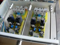
Construction:
http://images1.hiboox.com/images/2907/tjyuig2z.jpg
Transformers fixations have been changed later with a solid one
http://images1.hiboox.com/images/2907/io8xpmzi.jpg
http://images1.hiboox.com/images/2907/34nxaij1.jpg
Manuel soft-start with 3 positions switch Off – Soft-start – On
http://images1.hiboox.com/images/2907/srac5882.jpg
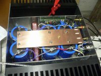
Main board
http://images1.hiboox.com/images/2907/9blybhvp.jpg
Pot. for bias et ac-current gain
http://images1.hiboox.com/images/2907/0koo73fv.jpg
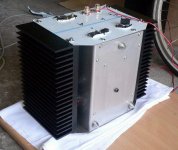
A heatsink
http://images1.hiboox.com/images/2907/rynxctx0.jpg
Rectifier with 4 x mur3020WT and thermal switch 75°C:
http://images1.hiboox.com/images/2907/xa7tcrj9.jpg 11
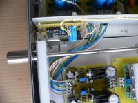
Wiring
http://images1.hiboox.com/images/2907/usyzp1ft.jpg
Tore self 2,2mH
http://images1.hiboox.com/images/2907/82eobyan.jpg
Bleeder résistors 2x10K
http://images1.hiboox.com/images/2907/6j4abjau.jpg
The same before
http://images1.hiboox.com/images/2907/ow07tzeo.jpg
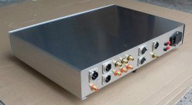
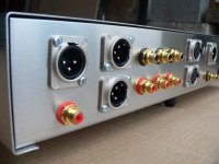
Main board, connect and unbalanced-balanced switch (in- to gnd)
http://images1.hiboox.com/images/2907/qkihepe2.jpg
Cheers, Laurent
(You see, Cheff, I posted the photos finally)
For the fun, some additional photos of amp (better quality):
The same before:
http://images1.hiboox.com/images/2907/no8rvhhk.jpg
http://images1.hiboox.com/images/2907/4tb39w3a.jpg
http://images1.hiboox.com/images/2907/oj070lv2.jpg
Construction:
http://images1.hiboox.com/images/2907/tjyuig2z.jpg
Transformers fixations have been changed later with a solid one
http://images1.hiboox.com/images/2907/io8xpmzi.jpg
http://images1.hiboox.com/images/2907/34nxaij1.jpg
Manuel soft-start with 3 positions switch Off – Soft-start – On
http://images1.hiboox.com/images/2907/srac5882.jpg
Main board
http://images1.hiboox.com/images/2907/9blybhvp.jpg
Pot. for bias et ac-current gain
http://images1.hiboox.com/images/2907/0koo73fv.jpg
A heatsink
http://images1.hiboox.com/images/2907/rynxctx0.jpg
Rectifier with 4 x mur3020WT and thermal switch 75°C:
http://images1.hiboox.com/images/2907/xa7tcrj9.jpg 11
Wiring
http://images1.hiboox.com/images/2907/usyzp1ft.jpg
Tore self 2,2mH
http://images1.hiboox.com/images/2907/82eobyan.jpg
Bleeder résistors 2x10K
http://images1.hiboox.com/images/2907/6j4abjau.jpg
The same before
http://images1.hiboox.com/images/2907/ow07tzeo.jpg
Main board, connect and unbalanced-balanced switch (in- to gnd)
http://images1.hiboox.com/images/2907/qkihepe2.jpg
Cheers, Laurent
(You see, Cheff, I posted the photos finally)
I don’t know UPS. Caps are C039/C114 series from ‘’BC Components’’ (old name = Philips). The size of these 22KµF-63V is similar to 47KµF-63V standard series. I choose them because high current, very low resist. They have dents effectively:
http://www.electronique-diffusion.fr/images/ph_internet_zoom/032774.jpg
Laurent
http://www.electronique-diffusion.fr/images/ph_internet_zoom/032774.jpg
Laurent
- Status
- This old topic is closed. If you want to reopen this topic, contact a moderator using the "Report Post" button.
- Home
- Amplifiers
- Pass Labs
- Thanks Mr Pass for my Aleph 2 and UGS diy