lykkedk said:
ZenMod ? I don't understand this
..............
congrat's ........
post No. 500
later
lykkedk said:............
Could you perhaps give me some meassuring point or any thing i can chase for
I now have no clue where to look.
Jesper.
check (set) voltages across R24 and R22 ; then fiddle with both WRs iteratively ;
check other voltages too ; if problem still persist we'll find what's in case
Attachments
ya greedy lazy crazy yank
how nice. Thanks!
ya need entire article?
Why not??
")
Godmorning ZenMod
My ongoing chase this morning :
I tried to meassure the value's, and they are ~the same...
1. 4v76 from R14 to +36 i have the same.
11v58 across C6 ~same
1v35 across R24 i have 1,2v
2v88 across R22 i have 2,65v
Output GND -out = 17vdc / GND +out 17vdc (still before caps) between +/- 50mV
I figured out, when connecting -in to GND i have a nice outputswing at ~8v between +out / -out (after cap's) So i am getting some gain now!
Is the pumpkin inverting +in to -out ?
How much schould it swing 1v sine excatly ?
I will go on hunting later today... thanks for your'e efford.
Jesper-
lykkedk said:Godmorning ZenMod
My ongoing chase this morning :
I tried to meassure the value's, and they are ~the same...
1. 4v76 from R14 to +36 i have the same.
11v58 across C6 ~same
1v35 across R24 i have 1,2v
2v88 across R22 i have 2,65v
Output GND -out = 17vdc / GND +out 17vdc (still before caps) between +/- 50mV
I figured out, when connecting -in to GND i have a nice outputswing at ~8v between +out / -out (after cap's) So i am getting some gain now!
Is the pumpkin inverting +in to -out ?
How much schould it swing 1v sine excatly ?
I will go on hunting later today... thanks for your'e efford.
Jesper-
you must leave it on few hours before final settings ;
nota bene- if pcbs are in case , you must tweak it with cover removed just for fast tweedle with WRs .
almost all values are ok , except offsets between outputs and gnd ;
try to vary resistor values in sources of Q6 and Q8 ......decrease them slightly ............. say 5-10% ;
those CCSes seems aren't open enough
what's your setup?
for setting- ground both inputs;
if you use unbal input- you must ground neg input ;
same with output........... if you use unbal out- ground neg output
Which is the thing giving the gain right ?those CCSes seems aren't open enough
I will use unbalanced input through stereopot 4,7k ohm alps. Output should be balanced to my 2pcs. F4 mono's.what's your setup?
I have to do this, while trimming and adjustning the pumpkin ?for setting- ground both inputs;
I will now go and place the final heatsink's on pumpkinpcb, and leave it on for some hour's. When done i will do this.
try to vary resistor values in sources of Q6 and Q8 ......decrease them slightly ............. say 5-10% ;
Jesper.. (I am getting there
)lykkedk said:
Which is the thing giving the gain right ?
everything is giving the gain..... frankly- I don't understand this question
gain is set with 10K/100K resistor net on input (100K from output) ...so gain is 10
I have to do this, while trimming and adjustning the pumpkin ?
yes .......... or just properly place pot on input , and turn it down all the way.
everything is giving the gain..... frankly- I don't understand this question
gain is set with 10K/100K resistor net on input (100K from output) ...so gain is 10
Uppss... i did it again...
ZenMod i just thought that the gain would be more than 10 times, therefore i thought that q6 / q8 was giving gain/outputswing. I sure understand why you didn't understud my quistion..
Back to heatsinkwork.
Attachments
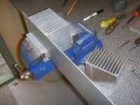
mpmarino said:Why are you squishing a perfectly good heatsink in a vise?

crazy danske

lykkedk said:It would look
Jesper. / Skål
you mean "pigs"
Morning...
Everything is different, with 10k pot attached between +in and GND, and -in and GND shorted.
After 1hour warm up. (Not getting hot - psu slightly more heat)
Next channel will be mounted on top of first one. (See picturelink below)
+out ---> GND : within mV (0-250)
-out ---> GND : Same
Between +out -out : in 100mV range...
All before outputcap's ofcause.
Across R27/270ohm : 1,2vdc (Ref. value = 1v35)
Across C6 : 11,23vdc (Ref. value = 11v58)
Across R22/180ohm : 2,87vdc (Ref. value = 2v88)
Between +36 and R14 : 5vdc (Ref. value = 4v76)
Setup is slightly stabilising now i see!
ZenMod Gain is 10. Is that correct (Eg. Balanced out +out/-out. 1v-sine in will come out with 10v-sine. 2v in gives 20v out etc...) ???
I actually bellived that would deliver much more, or maybee i am mistaken something
I can't upload picture's right now, so please visit My site
Jesper.
Everything is different, with 10k pot attached between +in and GND, and -in and GND shorted.
After 1hour warm up. (Not getting hot - psu slightly more heat)
Next channel will be mounted on top of first one. (See picturelink below)
+out ---> GND : within mV (0-250)
-out ---> GND : Same
Between +out -out : in 100mV range...
All before outputcap's ofcause.
Across R27/270ohm : 1,2vdc (Ref. value = 1v35)
Across C6 : 11,23vdc (Ref. value = 11v58)
Across R22/180ohm : 2,87vdc (Ref. value = 2v88)
Between +36 and R14 : 5vdc (Ref. value = 4v76)
Setup is slightly stabilising now i see!
ZenMod
Gain is 10. Is that correct (Eg. Balanced out +out/-out. 1v-sine in will come out with 10v-sine. 2v in gives 20v out etc...) ???I actually bellived that
would deliver much more, or maybee i am mistaken something I can't upload picture's right now, so please visit My site
Jesper.
lykkedk said:Morning...
Everything is different, with 10k pot attached between +in and GND, and -in and GND shorted.
After 1hour warm up. (Not getting hot - psu slightly more heat)
Next channel will be mounted on top of first one. (See picturelink below)
+out ---> GND : within mV (0-250)
-out ---> GND : Same
Between +out -out : in 100mV range...
All before outputcap's ofcause.
Across R27/270ohm : 1,2vdc (Ref. value = 1v35)
Across C6 : 11,23vdc (Ref. value = 11v58)
Across R22/180ohm : 2,87vdc (Ref. value = 2v88)
Between +36 and R14 : 5vdc (Ref. value = 4v76)
Setup is slightly stabilising now i see!
...........
I'm glad that morning is really good for you
ZenMod
I actually bellived that
you are really greedy crazy danske .....
push more voltage in , and
will spit nearly 70V out.......OK- not exactly 70 but little less
anyway- you can alter gain with ratio of R1/R5 and R3/R6 ;
try with 8K2/150K to nearly double spitting out ....... and that will certainly make your F4s to earn their money

observe clipping with CRO, just because I didn't remember what OLG was and I'm too lazy now to calculate ;
contrary to Papa, my every day is bad math day edit:
you can cut those heatsinks once more in half and use them for other channel ;
you don't need so big 'sinks from many reasons ........ box can be smaller and also output mosfets like when they're little toastier .......
editedit:
gimme first pic more clearly and bigger ........ I wanna see those leds nicely
editeditedit:
when you finish other channel and make some listening , you owe sixpack to Lucky Luke ;
maybe another one to danske metalman,too ........
gimme first pic more clearly and bigger ........ I wanna see those leds nicely
Here you GO
Thank you man... really glad helping me out!
you can cut those heatsinks once more in half and use them for other channel ;
you don't need so big 'sinks from many reasons ........ box can be smaller and also output mosfets like when they're little toastier
Yep... I think you maybee misunderstud me. The other channel will be placed on top of the 1. pcb... After that i can cut the 'Dept' of the heatsink off, so tempure will be higher. The sink placed left, is only for PSU. Anyway, they sit on back of rather small chassis, so it look's cool with them there.
anyway- you can alter gain with ratio of R1/R5 and R3/R6 ;
try with 8K2/150K to nearly double spitting out .......
observe clipping with CRO, just because I didn't remember what OLG was and I'm too lazy now to calculate ;
Cool i will try it out.. Zenmod what is CRO / OLG ???
Jesper.
lykkedk said:
Here you GO
Thank you man... really glad helping me out!
Yep... I think you maybee misunderstud me. The other channel will be placed on top of the 1. pcb... After that i can cut the 'Dept' of the heatsink off, so tempure will be higher. The sink placed left, is only for PSU. Anyway, they sit on back of rather small chassis, so it look's cool with them there.
Cool i will try it out.. Zenmod what is CRO / OLG ???
Jesper.
I already saw that picture ; I wanna bigger
- now I understand how you'll place pcbs .... OK ;
CRO is your scope .... http://lykkeserver.googlepages.com/Pumpkininput1v.jpg/Pumpkininput1v-full.jpg
OLG is Open Loop Gain ............ CLG is Closed Loop Gain ....... meaning that CLG must be (in most cases) substantially lower than OLG , except when you choose from first step in construction to make "non feedback stage" meaning (in most cases) on overall feedback loop......
clear 'nuff?
I already saw that picture ; I wanna bigger
Hehe... i think you gotta roll down the side, there is a big picture called led's for zenmod... (or do you need other picture now, then just tell and i will do) Later i will post more picture's...
OLG is Open Loop Gain ............ CLG is Closed Loop Gain ....... meaning that CLG must be (in most cases) substantially lower than OLG , except when you choose from first step in construction to make "non feedback stage" meaning (in most cases) on overall feedback loop......
Sort of understand that. !
Jesper.
BTW: thoose beer, i will certantly not forget... thrust me ZenMod
lykkedk said:
Hehe... i think you gotta roll down the side, there is a big picture called led's for zenmod... (or do you need other picture now, then just tell and i will do) Later i will post more picture's...
.............

- Home
- Amplifiers
- Pass Labs
- Pumpkin Preamp - Perfect for F4