Your 25K inuput resistor is too high. As it stands, your feedback current will overwhelm your input giving you alot less than the 2x gain you're looking for. The current will flow from the feedback through the volume pot since it is lower resistance the the 1M ground reference resistor. This will also make a variable gain circuit, with gain reducing as you attempt to increase volume. I know because I built one (see 12 posts above). I ended up putting a 4.7K resistor to ground instead of 1M, but that affects the input impedance. My recommendation would be to increase the series input resistor and feedback resistor to about 10x or 20x what they are currently.
I tried with more value for the feedback loop and series resistor, but the high frequency rolloff is huge. Probably the global feedback loop isn't a good idea. In the schematic that I added before, the value of the power supply is too low, I was trying other values (Simulation) and the original 30V to 35V looks the right value, by changing the 1N4747 to a 1N4754 and 30VAC transformer.
The change of R10 from 10 Ohm to 20 Ohm or more increases the distortion, like the change of R7 to 1K.
I'm out of ideas for get less gain with the same amount of distortion (Best less).

Question on volume control
I have finished assembling a jBOZ with a 16V power supply. Pretty much the standard schematic with 25K trimpot and 1M resistor at the input of the preamp.
Amp sounds wonderful. I want to be able to control the gain of the preamp. The amp connects to a F5 and therefore I do not want to put a volume pot at the output of jBOZ. I am planning to connect a volume pot at the input of jBOZ.
Should I remove the 25K trimpot and put a volume control in it's place or can I add a volume control in front of the trimpot. If yes, what value should it be.
Thanks.
Yes, you must remove the trimpots if you uses a pot. 20K or 25K pot is ok. (The trimpots on original schematic are intended for gain control, but if you use a pot instead the trimpots, these trimpots haven't nonsense.)
I did some simulations and looks that the boz works better with a 30 to 35V supply, I'm waiting capacitors of more voltage for try it.
Happy listening!
18V across a k170 is a lot.
Thanks Andrew, this is based on papas design http://www.diyaudio.com/forums/pass-labs/103050-jfet-boz.html#post1226446, which is the maximum voltage that you would use?.
Last edited:
read what JC says about gate leakage current at high Vds.
The datasheet graph also gives some idea of how this varies.
Thanks Andrew, I'm trying to find "gate leakage current at high Vds" but looking the K170's datasheet, 18V and 6,5mA appears not bad (I can easily be mistaken
. I have paid attention to this post of this thread http://www.diyaudio.com/forums/pass-labs/103050-jfet-boz-58.html#post1547881
P.S. With my prototype 16.3V looks too low, I get 1% of THD at 1.4V rms
Last edited:
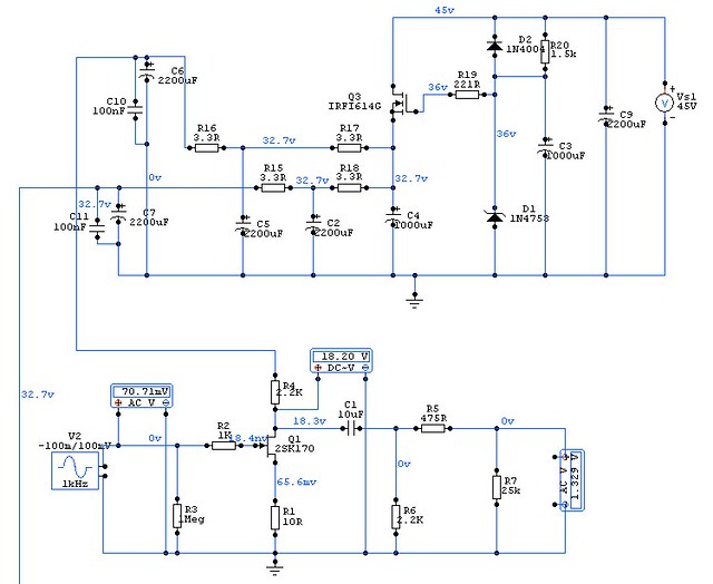
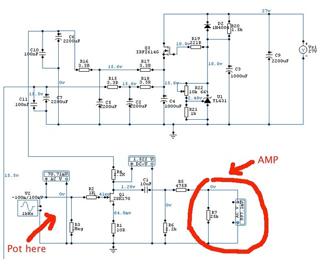
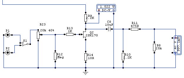
After several turns around the boz (Raising the voltage, feedback loop, more value to the source resistor, less value the supply resistor .....), I left the boz like is. I found that is very critic to the supply alimentation, for my 8mA IDSS 2SK170BL the best value for the lowest distortion is 15,55V, I changed the zener to a TL431 with pot (For a fine tuning).
The schematic
An externally hosted image should be here but it was not working when we last tested it.
The schematic
After several turns around the boz (Raising the voltage, feedback loop, more value to the source resistor, less value the supply resistor .....), I left the boz like is. I found that is very critic to the supply alimentation, for my 8mA IDSS 2SK170BL the best value for the lowest distortion is 15,55V, I changed the zener to a TL431 with pot (For a fine tuning).

The schematic
I am using a similar board. If I understood your post, you removed the 25k trimmer pot at the input and replaced with a step attentuator of similar value as volume control isn't it? You also seem to have 3 input with selector switch. Any passive network used there?
Thanks.
I am using a similar board. If I understood your post, you removed the 25k trimmer pot at the input and replaced with a step attentuator of similar value as volume control isn't it? You also seem to have 3 input with selector switch. Any passive network used there?
Thanks.
Yes, I didn't used the board potentiometers and I added a 20K step attenuator. The selector are a 2 Way 6 positions, but I use just two. Also I changed the zener by a TL431 on a small board.
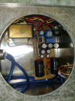
I use all wires with screen for get the best crosstalk, but the earth of the inputs is conected to the output conector and these to the board.
This is the input:
And this is the 431 board:
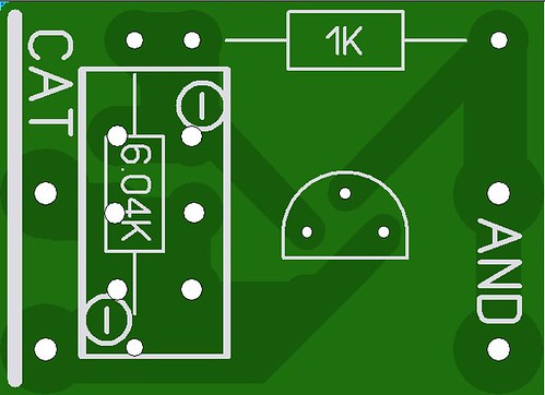
431 layout
431
Very nice
Manu
Thanks Manu,
I had a big surprise when I started to read this thread and I saw that this chinese pcb is a copy of your pcb.
Thanks for your pcb design!
OK...I built mine apparently with 2sk370's originally must be thats what I had laying around....
So one channel had been going wonky and I ruled out the coupling caps and everything else but the JFETS...It has a lot of hours on it so I figured lets change out the JFETS and see if that helps...
All I have left now are a handful of 2sk170s so I plopped a pair in. Distortion city!!! These are the BL type but with the source and drain resistors I had in place all I could eek out of them was 6ma.
I dropped the drain resistor to 1K from 2.2K and dropped the source resistor down to 5 ohms(all I had was another pair of 10ohm resistors).
This cranked the 2sk170s up to about 8.5mA and boy is the sound sweet again!!!
I took the old JFETBOZ out and just plugged the ipod into the F4(with integrated BA2 front end) and while it sounded great the gain was just quite not enough....
Now with the JFETBOZ back in action all is right with the world again!
If it weren't for Diyaudio I would never know where to immediately hone in to troubleshoot this awesome little preamp. THANK YOU!
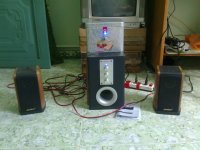
Hello everyone! after the reference and read all 104 pages of the pre JFET Boz, I decided to install this pre discount.
Map that I choose to do is follow the plan of ramallo because my transformers and capacitors suitable voltage. when done, I tried the pre transplant with my computer speakers.
Unexpectedly! JFET with two children but that the sound quality of this pre show or out of my imagination. Bass is deep and warm voice is smooth and rustic MID, also known TRELLE the towering and clear to the exotic.
Before I installed the pre this was my computer speakers are performing normally and faint. but when the pre transplant into the speakers of my computer completely makeover scholarship and I am extremely interested in the pre this.
Please thank Nelson PASS and everyone on the forum was to share knowledge and experience for me.
because my English ability is very bad so I used google translate to translate it a bit confusing. expect people to sympathize.
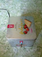
And here's a picture of my pre Boz JFET
Map that I choose to do is follow the plan of ramallo because my transformers and capacitors suitable voltage. when done, I tried the pre transplant with my computer speakers.
Unexpectedly! JFET with two children but that the sound quality of this pre show or out of my imagination. Bass is deep and warm voice is smooth and rustic MID, also known TRELLE the towering and clear to the exotic.
Before I installed the pre this was my computer speakers are performing normally and faint. but when the pre transplant into the speakers of my computer completely makeover scholarship and I am extremely interested in the pre this.
Please thank Nelson PASS and everyone on the forum was to share knowledge and experience for me.
because my English ability is very bad so I used google translate to translate it a bit confusing. expect people to sympathize.
And here's a picture of my pre Boz JFET
Attachments
- Home
- Amplifiers
- Pass Labs
- Jfet BOZ