After reading the whole thread, I decided to try my hand at this design, but with a headphone amp in mind. I combined a JFET BOZ with a B1 and a mini Beast With a Thousand JFETs, plus a pinch of tube knowledge.
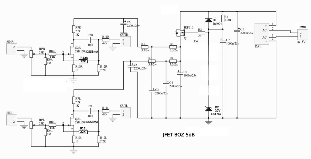
I've attached a schematic. It's a dual power supply design with a JFET gain stage and a JFET CCS on the Drain. There are three LEDs (2v drop each) to bring the value of the source resistor down to a reasonable value. This then goes into a B1 buffer but with five pairs of JFETs paralleled. Finally, a resistor provides feedback to minimize distortion and reduce gain down to 2. Right now the prototype proof of concept is playing fine on two 9v batteries. I built it with what I had laying around so the 20K resistor is only 18K and two of the 1meg resistors are 67K and the 600 ohms is 560, but those values are probably not too critical. It starts to distort pretty early, probably because I only used a single pair of JFETs on the output, so I only have few milliamps sourced through the CCS (I'm testing with hard to drive 34 ohm Sennheiser HD497s). I figure with five pairs in parallel I should be able to have 25-30 ma available which should drive most any reasonable headphone.
I'm wondering if the source resistor is the right size, it seems right for a load of about 5ma. The feedback seems to work, but could it be improved? Any thoughts on the overall design? I was wondering if I should bypass the LEDs with a capacitor to reduce the AC impedance, although it's probably only about 30-50 ohms with the old red LEDs I'm using. Constructive feedback is always appreciated.
Attachments
Hi Fenris,
I suppose you intend to use 2sk170 JFETs or similar ?
If it's so, it is unrealistic to expect from your SE output stage (B1) to drive 34 Ohms headphones (even with feedback).
Also, it is unclear why do you need the extra gain - few hundreds of mV will drive your headphones louder than you wish.
With low Z headphones you need your headamp to be capable of delivering the appropriate current into the load - search for DAO headamp, that will suit your headphones much, much better.
Yes, 2SK170s. The idea was to be flexible - some gain for high impedance headphones (gain of 2 should be sufficient and compensate for the non-unity gain of the source follower) and to have enough current for lower impedance headphones, which is why I would parallel 5 pairs on the output. Efficient? No, but I've got 15 pairs of matched JFETs sitting around without a home and an empty Altoids tin that needs a purpose in life.
i do not really think B1 is good for headphones, 5 parallel or not the output impedance is too high no? b1 buffer sounds very good, but its about as far from the ideal buffer as you can get ie. very high input z and very low output z. i could be wrong of course, but this also matches info i recieved when asking the same questions
Last edited:
Actually, high input impedance and low output impedance are traits of an ideal buffer. It's just that with only one pair of output devices the output impedance was only about 50 ohms - great for most line level stuff, but not really low enough for a pair of headphones, and definitely not low enough for 32 ohm headphones. When you parallel more (i.e. the Beast with 1000 JFETs), you drop the output impedance enough to drive output devices.
yeah but only 5? i wouldnt have thought that enough to raise the current to a sufficient level, or lower outputz to a low enough level. i suppose 5 will mean 35-50ma, enough, but not ideal imo. why not drop some lu1014d in there  or a touch more well measured feedback. ooops bad word
or a touch more well measured feedback. ooops bad word
Last edited:
The "average" audio op-amp used for most outputs like the 2132 or 627 have about 20ma of current capability with a 600 ohm load. Two and a half times the current capability will give five times the output power and the overall output impedance will be around 10 ohms. This probably isn't the "ideal" or "ultimate" solution, but I'm willing to try something unusual and unique. I could drop the 1014 in there, but I've already got enough 2sk170s that need a good home.
When you parallel more
For my headphone set i'd already be content with a 100 JFET beasty.

The "average" audio op-amp used for most outputs like the 2132 or 627 have about 20ma of current capability with a 600 ohm load. Two and a half times the current capability will give five times the output power and the overall output impedance will be around 10 ohms. This probably isn't the "ideal" or "ultimate" solution, but I'm willing to try something unusual and unique. I could drop the 1014 in there, but I've already got enough 2sk170s that need a good home.
and neither of those chips would go anywhere near satisfactorily powering my hd600 directly, not that i dont like the right opamps in the right design either, but both of those would need at the very least a high current buffer like buf634 or lme49600/10, a mosfet follower. etc and into lower ohms you will get considerably less power and bass will suffer big time
sure mate give it a go, sorry i'm really not trying to rain on your parade, i like seeing headphone users here on the forum, not enough of us. It just seems like a lot of effort to get what i would consider to be pretty subpar results with your headphones
and yes i'm a bad headphone geek. no reason you cant use those jfets, but you'll need more than 5 imo, a further gain stage, or current buffer; possibly some of EUVL's to92 heatsinks to crank a bit more juice out of the jfets??
When I get the prototype PCB back from the board house I'll populate it and let you know the results. I've got a mix of matched G and B 2SK170s, so I should be able to get at least 30 ma per channel. If it's still not enough, I'll have to try bigger JFETs or small FETs.
Your 25K inuput resistor is too high. As it stands, your feedback current will overwhelm your input giving you alot less than the 2x gain you're looking for. The current will flow from the feedback through the volume pot since it is lower resistance the the 1M ground reference resistor. This will also make a variable gain circuit, with gain reducing as you attempt to increase volume. I know because I built one (see 12 posts above). I ended up putting a 4.7K resistor to ground instead of 1M, but that affects the input impedance. My recommendation would be to increase the series input resistor and feedback resistor to about 10x or 20x what they are currently.
The type of resistors at position R7, R13 will have a direct effect on the sound so try a variety - metal, carbon, tantalum, Zfoils, etc - with these simple ccts, everything has an effect, inluding the current through the jfets, naturally.
Suggest reduce C5, C6 to about 220uF (another critical device) and can reduce C8 to about 4u7 and try Mundorf Supreme, etc.
... 2 cents
Suggest reduce C5, C6 to about 220uF (another critical device) and can reduce C8 to about 4u7 and try Mundorf Supreme, etc.
... 2 cents
You could have dropped the gain by increasing the source resistor. I have read where it is suggested the source resistor should be 20 ohms anyhow. This is local feed back so not as bad as global.
I tried with a 26,3 Ohm resistors and now the gain is 23,3dB, just dropped a bit, but isn't enough for my system. I'll try raise the value of these resistors.
In other hand, I think that for get more voltage swing at output the value of R12 must be increase and the value of R7 must be decrease, looks that both resistors acts like a tension divider. I think that R7 will be of 1K and R12=5K or more, am I on a mistake?.
Cheers
Last edited:
The type of resistors at position R7, R13 will have a direct effect on the sound so try a variety - metal, carbon, tantalum, Zfoils, etc - with these simple ccts, everything has an effect, inluding the current through the jfets, naturally.
Suggest reduce C5, C6 to about 220uF (another critical device) and can reduce C8 to about 4u7 and try Mundorf Supreme, etc.
... 2 cents
I'm using Vishay 1% 0,6W metal resistors, I tried with a Takman's carbon resistors at R11 and I didn't like the sound (Probably best with the metal ones). For capacitors I'm using Solen.
I added at C5 and C6 positions a small film capacitor in parallel (100nF)
P.S. In a B1 I used a 4u7 Mundorf silver in oil at output and I'm very happy with the result
- Home
- Amplifiers
- Pass Labs
- Jfet BOZ